Blinded by the Light: DIY Retinal Projection

Retinal Projection

After grabbing a couple of Microvision SHOWWX laser picoprojectors when they went up on Woot a few months back, I started looking for ways to use them.  Microvision started out of a project at the University of Washington HITLab in 1994 to develop laser based virtual retinal displays.  That is, a display that projects an image directly onto the user’s retina.  This allows for a potentially very compact see through display that is only visible by the user.  The system they developed reflected lasers off of a mechanical resonant scanner to deflect them vertically and horizontally, placing pixels at the right locations to form an image.  The lasers were modulated to vary the brightness of the pixels.  The SHOWWX is essentially this setup after 15 years of development to make it inexpensive and miniaturize it to pocket size.  The rest of the retinal display system was a set of optics designed to reduce the scanned image down to a point at the user’s pupil.  I thought I would try to shrink and cheapen that part of it as well.

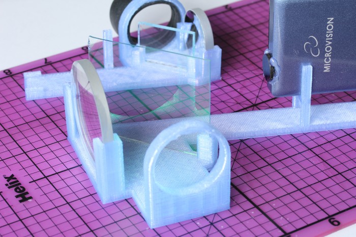
The setup I built is basically what Michael Tidwell describes in his Virtual Retinal Displays thesis.  The projected image passes through a beamsplitter where some of the light is reflected away, reflects off of a spherical concave mirror to reduce back down to a point, and hits the other side of the beamsplitter, where some of the light passes through and the rest is reflected to the user’s pupil along with light passing through the splitter from the outside world.  For the sake of cost savings, all of my mirrors are from the bargain bin of Anchor Optics.  The key to the project is picking the right size and focal length of the spherical mirror.  The larger setup in the picture below uses a 57mm focal length mirror, which results in a fairly large rig with the laser scanner sitting at twice the focal length (the center of curvature) away from the mirror.  The smaller setup has a focal length around 27mm, which results in an image that is too close to focus on unless I take my contact lenses out.  The mirror also has to be large enough to cover most of the projected image, which means the radius should be at least ~0.4x the focal length for the 24.3° height and at most ~0.8x for the 43.2° width coming from a SHOWWX.  Note that this also puts the field of view of the virtual image entering the eye somewhere between a 24.3° diameter circle and a 24.3° by 43.2° rounded rectangle.

Projection Rig

Aside from my inability to find properly shaped mirrors, the big weakness of this rig is the size of the exit pupil.  The exit pupil is basically the useful size of the image leaving the system.  In this case, it is the width of the point that hits the user’s pupil.  If the point is too small, eye movement will cause eye pupil to miss the image entirely.  Because the projector is at the center of curvature of the mirror (see the optical invariant), the exit pupil is the same the width as the laser beams coming out of the projector: around 1.5 mm wide.  This makes it completely impractical to use head mounted or really, any other way.  I paused work on this project a few months ago with the intention of coming back to it when I could think of a way around this.  With usable see through consumer head mounted displays just around the bend though, I figured it was time to abandon the project and publish the mistakes I’ve made in case it helps anyone else.

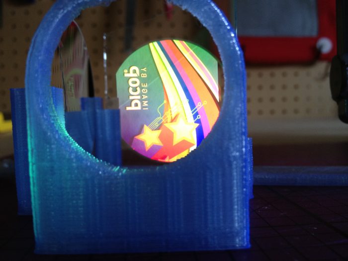
If you do want to build something like this, keep in mind that the title of this post is only half joking.  I don’t normally use bold, but this is extra important: If you don’t significantly reduce the intensity of light coming from the projector, you will damage your eyes, possibly permanently.  The HITLab system had a maximum laser power output of around 2 μW.  The SHOWWX has a maximum of 200mW, which is 100,000x as much!  Some folks at the HITLab published a paper on retinal display safety and determined that the maximum permissible exposure from a long term laser display source is around 150 μW, so I needed to reduce the power by at least 10,000x to have a reasonable safety margin.  As you can see in the picture above, I glued a ND1024 neutral density filter over the exit of the projector, which reduces the output to 0.1%.  Additionally, the beamsplitter I picked reflects away 10% of the light after it exits the projector, and 90% of what bounces off of the concave mirror.  Between the ND filter, the beamsplitter, and setting the projector to its lowest brightness setting, the system should be safe to use.  The STL file and a fairly ugly parametric OpenSCAD file for the 3D printed rig to hold it all together are below.

blinded.scad
blinded.stl

14 Comments on Blinded by the Light: DIY Retinal Projection

Reverse Engineering the Lytro .LFP File Format

Lytro Microlens Array

After getting my Lytro camera yesterday, I set about answering the questions about the light field capture format I had from the last time around.  Lytro may be focusing (pun absolutely intended) on the Facebook using crowd with their camera and software, but their file format suggests they don’t mind nerds like us poking around.  The file structure is the same as what they use for their compressed web display .lfp files, complete with a plain text table of contents, so I was able to re-use the lfpsplitter tool I wrote earlier with some minor modifications.  The README with the tool describes in detail the format of the file and how to parse it.

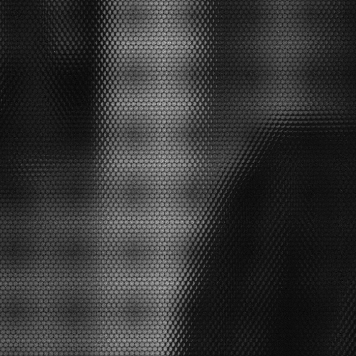
The table of contents in the raw .lfp files gives away most of the camera’s secrets.  It contains a bunch of useful metadata and calibration data like the focal length, sensor temperature, exposure length, and zoom length.  It also gives away the fact that the camera contains a 3 axis accelerometer, storing the orientation of the camera with respect to gravity in each image.   The physical sensor is 3280 by 3280 pixels, and the raw file just contains a BGGR Bayer array of it at 12 bits per pixel.  Saving the array and converting it to tif using the raw2tiff command below shows that each microlens is about 10 pixels in diameter with some vignetting on the edges.

raw2tiff -w 3280 -l 3280 -d short IMG_0004_imageRef0.raw output.tif

Syncing the camera to Lytro’s desktop software backs it up the first time.  Amazingly, the backup file uses the same structure as both .lfp file types.  The file contains a huge amount of factory calibration data like an array of hot or stuck pixels and color calibration under different lighting conditions.  Incredibly, it also lets loose that there is functioning Wi-Fi on board the camera with files named “C:\\CALIB\\WIFI_PING_RESULT.TXT” and “C:\\CALIB\\WIFI_MAC_ADDR.TXT”, which matches what the FCC teardowns show.  There is no mention of Bluetooth support though, despite support by the chipset.  In any case, it seems there is a lot of cool stuff coming via firmware updates.

Hopefully one of those updates enables a USB Mass Storage mode, as there does not appear to be any way to get files off of the camera in Linux. I had to borrow my roommate’s MacBook Air for this escapade. The camera shows up as a SCSI CD drive, but mounting /dev/sr0 only shows a placeholder message intended for Windows users.

Thank you for purchasing your Lytro camera.  Unfortunately, we do not have a
Windows version of our desktop application at this time.  Please check out
http://support.lytro.com for the latest info on Windows support.

It was pretty trivial to write the lfpsplitter to get the raw data shown above, but doing anything useful with it will take more effort.  Normally simple stuff like demosiacing the Bayer array will likely be complicated by the need to avoid the gaps between microlenses and not distort the ray direction information.  Getting high quality results will probably also require applying the calibration information from the camera backups.  A first party light field editing library would be wonderful, but Lytro probably has other priorities.

You can grab my lfpsplitter tool from GitHub at git://github.com/nrpatel/lfptools.git and I uploaded an example .lfp you can use with it if you want to play with light field captures without the $400 hardware commitment.

68 Comments on Reverse Engineering the Lytro .LFP File Format

Semi-Automatic Paintbrush

The Mona Lisa

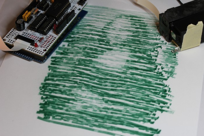
I bought an InkShield from the Kickstarter a few months ago mostly out of a desire to support an interesting Open Hardware project.  It wasn’t until yesterday that I thought of something useful to do with it.  Instead of that, I made this project, called the Semi-Automatic Paintbrush.  Using an infrared camera, an InkShield, an ink cartridge with an infrared LED stuck to it, and your arm, you can copy great works of art, or just any old picture.

The desktop side software involved is called paintbrush.py.  It conveniently uses the homography module I wrote a year ago to map what the IR camera sees to the coordinate system of the canvas.  The mapping is calibrated interactively by placing the cartridge/LED at each of the four corners of the canvas and pressing a key when prompted.  After that, the motion of the LED is tracked, the corresponding region of the image is found, and the script sends serial commands to an Arduino with the InkShield telling it which nozzles to fire at what duty cycle to achieve the correct level of gray, or in this case, green.  The painted regions are tracked to prevent flooding.

As you can see from the image above, the results are not going to end up in the Louvre, but they do have a kind of partially mechanical, partially organic flavor to them.  If you have an InkShield, an IR LED, and a pygame supported IR camera (I use a modified PS3 Eye), and you’re interested in making your own lazy artwork, the script is available on github under an ISC License.  The Arduino sketch requires the InkShield library and is LGPL.  Usage instructions for the script are contained with it.

5 Comments on Semi-Automatic Paintbrush

Augmented Reality for 3D Printing

Yoda
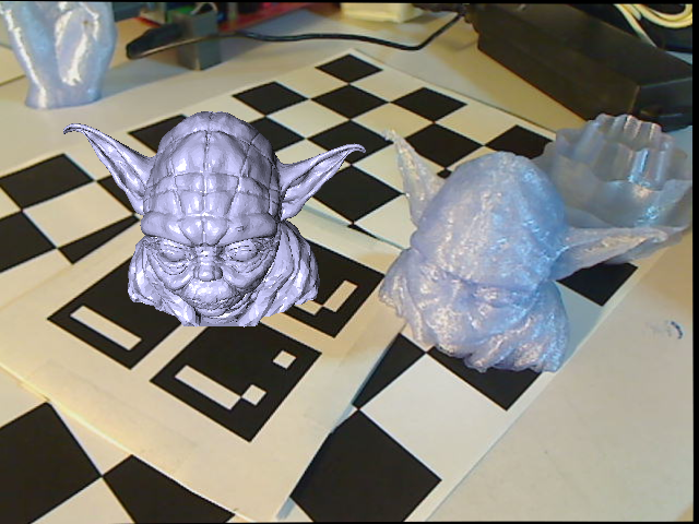
My roommate’s struggles designing his first 3D printed part gave me the idea to write an augmented reality viewer that lets you preview and interact with STL models in the real world without having to commit an object to plastic. This is actually sort of an update on part of a project I did for a Computational Photography course three years ago, but not terrible looking this time. I used the ArUco library to track the fiducial markers, largely because there is a javascript version if I ever want to make it web based. The program, which I uncreatively named arstl, reads in ASCII and binary STL files and displays them on top of the tracked marker. Right now, it uses a pretty basic OpenGL shader for a shiny plastic look, but I plan on making a more convincingly plastic one with bump mapping and subsurface scattering soon. As usual, the code is up on github under an ISC License. The STL parsing part of it is in the public domain, in case anyone finds it useful.

2 Comments on Augmented Reality for 3D Printing

Thoughts on the Lytro Light Field Camera

Lytro recently made its namesake light field camera available for preordering. The light field camera reaches closer to the plenoptic function than a standard camera in that instead of only summing the photons to arrive at chromacity and luminosity at each pixel, it additionally determines directional information. It does so by placing an array of microlenses above the sensor, each of which represents a light field pixel and covers a region of sensor pixels. Each sensor pixel then captures a ray arriving at a specific direction at its parent microlens. Ren Ng’s thesis is full of fascinating uses for this, but it seems Lytro is primarily focusing on the ability to refocus the light field image.

There is very little information available about the format the camera is capturing the light field in, but I suspect that it will not be impossible to use the files for other purposes like viewing parallax and perspective changes on a single capture. So far, the information we have is that the 8 gigabyte model can store 350 images, the sensor can capture 11 megarays, and the examples in the online gallery have resolutions of 831×831 to 1080×1080. Since the sensor in a light field camera captures one ray per pixel, we can assume the physical sensor is 11 megapixels. Conveniently, 350 11 megapixel images of 2 bytes per pixel add up to roughly 8 gigabytes. This suggests the format may be either a raw 16 bit Bayer array off of the sensor or a processed and packed RGB array. As for the microlens array, I suspect that it is a roughly 831×831 grid of hexagonal lenses, each of which cover a roughly 16 square pixel area, for a total sensor resolution of 3324×3324 pixels. We probably won’t know for sure until the cameras ship in early 2012.

In the meantime, we do have some sample images to play with, but not in the format captured by the camera. The Lytro desktop app apparently exports compressed representations of the light field to reduce file sizes and rendering requirements for web display. The .lfp files are simply a set of JPEGs representing the unique visually interesting sections of the light field. That is, a set in which each image shows a different area in focus. It appears to do so dynamically, picking the minimum number of images necessary to show all focusable objects in narrow depths of field. These images are stored along with their estimated depths and a depth lookup table for the image. This allows for HTML5 and Flash applications like the one embedded above in which the user clicks on a region of the image, the value of that region is looked up, and the depth image closest to that value is displayed.

To allow for viewing the files offline and to satisfy my curiosity, I wrote a tool called lfpsplitter that reads in an .lfp and writes out its component images as .jpg files and the depth lookup table and image metadata as plain text files. It is available on github, along with a README describing the file format in detail. Until we have Lytro cameras and .lfp files of our own to play with, you can find example files by examining the html source of Lytro’s gallery page.

Update: Given the animated parallax shift image of Walt Mossberg on the Lytro blog, it seems that each microlens covers an area 5 pixels across horizontally. Perhaps the sensor is 4096×4096 and 11 megarays describes the number of pixels getting useful photons, or the microlenses are arranged in a honeycomb pattern with a maximum width of 5px.

2 Comments on Thoughts on the Lytro Light Field Camera

Thingidiff: Visualizing 3D Model Diffs with Thingiview.js

Thingidiff

Thingiverse is an enormous resource for mostly open source, ready to print 3D objects.  It conveniently has both a built in understanding of derivative objects and a web based 3D object viewer.  It has no mechanism for combining the two though, making comparing any two objects a matter of either visual guesswork or downloading and comparing the files against each other.

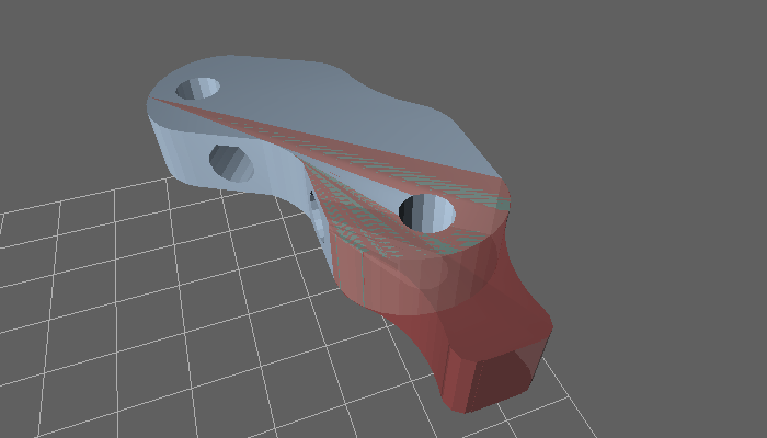
Thingidiff is my fork of Thingiview.js allowing for web based visual comparisons between related 3D objects.  Colors and opacities can be set for faces that are the same in both objects or unique to one or the other.  The obvious use cases for this are showing a diff between a derived object and its original or showing differences in revisions of a work in progress.  Both of these cases are in evidence on the example page.  Note that between this being my first project in Three.js or Javascript at all and the currently mercurial state of WebGL support in web browsers, there are probably going to be nits, bugs, or even outright computer exploding failures in your experience.  I’m interested in bug reports though, if you would be willing to drop them on the github project’s Issues page.  The code itself is nearby.

1 Comment on Thingidiff: Visualizing 3D Model Diffs with Thingiview.js

Satellites on a Snow Globe Spherical Display

Continuing on the theme of interesting things to do with an interactive globe, I added a live satellite tracking mode to sosg.  The program polls a local PREDICT server for location and visibility information about the satellites being tracked by it.  It draws the name of each satellite and the path it is following in red.  It also draws a little icon that turns green when the satellite is visible overhead. There is enough civilization in close proximity to my apartment that I can’t see actually see one pass by, but it is nice to know they are there above me.  As before, the ISC licensed code is available on github at git://github.com/nrpatel/SnowGlobe.git

9 Comments on Satellites on a Snow Globe Spherical Display

Science on a Snow Globe Spherical Display

Science On a Sphere is a NOAA project typically using four projectors to display planetary data on a six foot diameter sphere.  As a federal agency, NOAA publishes data that is not copyrightable.  These public domain datasets are pretty impressive, ranging from plate tectonics to solar storms.  They are also insanely high resolution, with mp4 videos and jpg images at 2048×1024 and 4096×2048.

To shrink this four projector, five computer, high resolution science center exhibit down to a picoprojector, old laptop, bathroom lighting fixture setup, I had to move beyond my unoptimized python scripts to SDL, OpenGL, libvlc, and GLSL.  I wrote a program called sosg, Science On a Snow Globe, which reads in images and videos and displays them in the correct format for Snow Globe.  Doing the equirectangular to fisheye transform in a fragment shader is extremely lightweight, even with GMA graphics.  Using libvlc makes video decoding quite performant as well, despite the resolution.

The program is the closest I’ve written to “shippable” in recent memory, but there are some rough spots.   I ran into a bottleneck trying to decode high resolution jpgs in real time, so currently sosg does not support the image slideshows that the full size SOS does.  It also doesn’t attempt to read in .sos playlist information.  Basically, it is not an SOS replacement, just a cheap and cheerful way to view planetary data on your desktop. Unlike the original, it is also available under a permissive license and can be cloned directly from git://github.com/nrpatel/SnowGlobe.git.

8 Comments on Science on a Snow Globe Spherical Display