Semi-Automatic Paintbrush

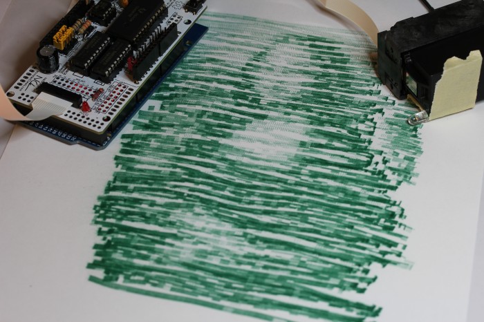
The Mona Lisa

I bought an InkShield from the Kickstarter a few months ago mostly out of a desire to support an interesting Open Hardware project.  It wasn’t until yesterday that I thought of something useful to do with it.  Instead of that, I made this project, called the Semi-Automatic Paintbrush.  Using an infrared camera, an InkShield, an ink cartridge with an infrared LED stuck to it, and your arm, you can copy great works of art, or just any old picture.

The desktop side software involved is called paintbrush.py.  It conveniently uses the homography module I wrote a year ago to map what the IR camera sees to the coordinate system of the canvas.  The mapping is calibrated interactively by placing the cartridge/LED at each of the four corners of the canvas and pressing a key when prompted.  After that, the motion of the LED is tracked, the corresponding region of the image is found, and the script sends serial commands to an Arduino with the InkShield telling it which nozzles to fire at what duty cycle to achieve the correct level of gray, or in this case, green.  The painted regions are tracked to prevent flooding.

As you can see from the image above, the results are not going to end up in the Louvre, but they do have a kind of partially mechanical, partially organic flavor to them.  If you have an InkShield, an IR LED, and a pygame supported IR camera (I use a modified PS3 Eye), and you’re interested in making your own lazy artwork, the script is available on github under an ISC License.  The Arduino sketch requires the InkShield library and is LGPL.  Usage instructions for the script are contained with it.

5 Comments on Semi-Automatic Paintbrush

Walk This Way: Pedestrian Traffic Light Status Indicator

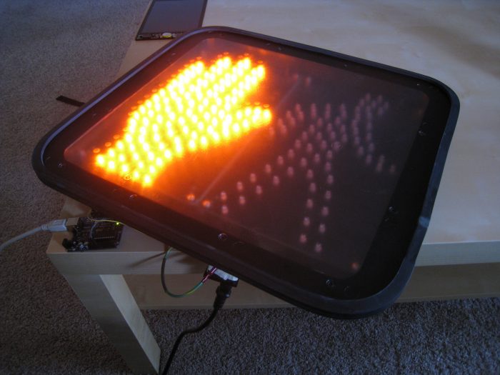
Traffic Sign Status Indicator

A recent Slashdot post about Weird Stuff Warehouse reminded me that they carry cheap pedestrian traffic lights. I’d been meaning to pick one up to use as a completely overkill status indicator at work.  I managed to get this one for $10. It is a GE PS7-CFC1-01A that uses LEDs and looks new, but was presumably dumped by the original owner because it is a basic stop/go light without a countdown timer or accessibility features.

Dual Power Supplies

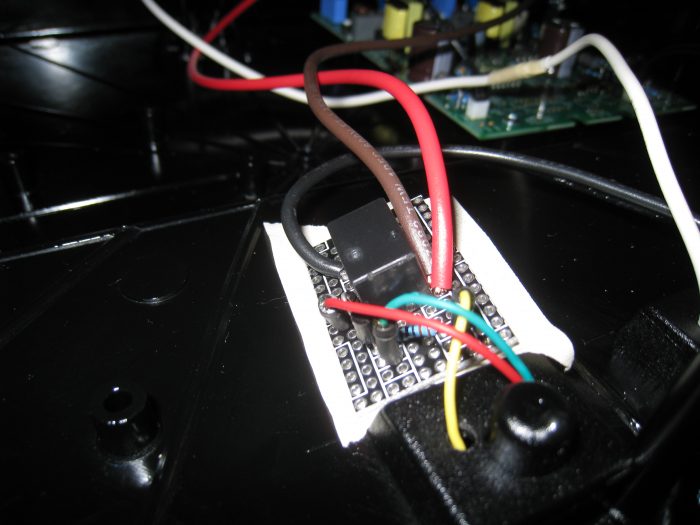
There were three mystery wires coming out of the back to interface it, so I cracked it open to see what was inside. The stop hand and walk person have independent AC-DC power supplies. Both halves share the white neutral wire, while each has a live wire of its own. The idea is to have the common line always connected to neutral while switching the hot line to whichever half you want lit up. Note that there is some additional circuitry on the right and an optoisolator connecting the halves. I believe this sign was designed such that if you attempt to power on both halves simultaneously, it will fail safe and light only the stop half.

Traffic Sign Relay

People often get their hearts broken on Valentine’s Day. Frying mine by playing with 120v AC is one way to do that. Kidding. Household AC is fine to tinker with as long as you’re careful. I built the circuit from the Arduino Relay guide to do the switching. I picked up a SPDT 5v power relay to make it easy to run off of the Arduino. The transistor is still necessary because the AVR can’t drive the 100+mA the relay needs to switch itself. I used an ATX power supply socket for convenience, rather than cutting a cable and using that. The neutral line from the socket is soldered to the neutral line on the sign. Each of the hot lines from the sign is connected to one of the relay throw positions, while the hot line from the socket is connected to the relay pole. Thus, toggling a pin high or low on the Arduino will flip the hot line from one half to the other, powering either the stop or go sign on. The project in total cost less than $20. It probably would have been under $15, but Radioshack is the only electronics store open on Sundays.

The code on the Arduino end is pretty simple. It just reads a character off the serial port and flips the relay one way or the other.

#define RELAY_PIN 13
bool state;
 
void setup()
{
  Serial.begin(9600);
  state = LOW;
  pinMode(RELAY_PIN, OUTPUT);
  digitalWrite(RELAY_PIN, state);
}
 
void loop()
{
  if (Serial.available()) {
    byte in = Serial.read();
    if (in == '0') {
      state = LOW;
      Serial.println("Switching relay to Stop.");
    } else if (in == '1') {
      state = HIGH;
      Serial.println("Switching relay to Go.");
    }
    digitalWrite(RELAY_PIN, state);
  }
}

The computer end can be whatever you want it to be. For example, in Python, you can use pySerial as follows.

>>> import serial
>>> sign = serial.Serial('/dev/ttyUSB0',9600)
>>> sign.write('0')
>>> sign.write('1')
1 Comment on Walk This Way: Pedestrian Traffic Light Status Indicator

Sleep Remaining Indicator: A Laser Alarm Clock

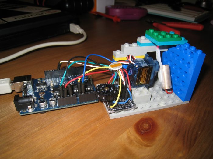
Sleep remaining indicator

The chunk of title after the colon intends to serve as an explanation of what a sleep remaining indicator is. However, this project is neither an alarm nor a clock. It is a visual indicator of approximately how much time I have remaining to sleep in the night.

This may not be a problem you need solved. If, however, like me you wear glasses or contacts, the world when you are in bed turns into a blurry mess. Normally I reach over and unlock my phone or lean over and squint at my Chumby One, but those actions make it harder to get back to sleep. What I wanted was a way to instantly know how much longer I could sleep before my alarm would go off.

My solution involves a line laser, a servo, and an Arduino. I set a potentiometer with a number dial to approximately the right length of time in hours and hit the reset button. The servo with the line laser attached will shine the laser line onto the ceiling. The servo will then slowly rotate, moving the laser line underneath a cover made of Lego pieces, making the length of line showing on the ceiling shrink over the hours. It’s a little like an hourglass, but with lasers.

Laser line

Here’s the Arduino sketch. Use it under whatever license you want.

/* Sleep Remaining Indicator v1.0
 * by Nirav Patel <http://eclecti.cc>
 */
 
#include <Servo.h>
#include <math.h>
 
//#define photoPin 1
//#define laserPin 9
#define potPin 0
#define servoPin 10
#define M_PI_4 (M_PI/4.0)
#define MINSERVO 1190 // The laser line is no longer visible
#define MAXSERVO 1810 // The laser line is at its longest
 
unsigned long startTime;
unsigned long totalTime;
unsigned int lastVal;
Servo laserServo;
 
void setup()
{
  Serial.begin(9600);
//  pinMode(photoPin, INPUT);
  pinMode(potPin, INPUT);
 
  // this magic converts the pot value to 0 to 9 hours in milliseconds.
  totalTime = (unsigned long)31641*(unsigned long)(1024-analogRead(potPin));
  Serial.print('Time in hours: ');
  Serial.println((double)totalTime/(double)3600000.0);
 
  laserServo.attach(servoPin);
  startTime = millis();
  lastVal = 0;
}
 
void loop()
{
  // The laser brightness should depend on the ambient light in the room.
  // Unfortunately, my laser dislikes PWM, so I just have it hooked to 3.3v
//  unsigned int light = analogRead(photoPin);
//  analogWrite(laserPin,light>>2);
 
  // calculate the time we've been running (well, sleeping)
  unsigned long time = millis()-startTime;
  // Note that one could use this as an alarm clock by setting off a buzzer or
  // even having the servo rotate loudly
  if (time > totalTime) {
    laserServo.writeMicroseconds(MINSERVO);
    while(1) {}
  }
 
  // This trig makes the line length shrink uniformly over time.
  time = totalTime-time;
  double angle = atan2((double)time,(double)totalTime);
  unsigned int servoVal =  (unsigned int)((angle/M_PI_4)*(double)(MAXSERVO-MINSERVO))+MINSERVO;
 
  servoVal = (servoVal > MAXSERVO? MAXSERVO : (servoVal < MINSERVO ? MINSERVO : servoVal));
  // The servo is imperfect, so don't move unless the value actually changed
  if (servoVal != lastVal) {
    Serial.println(servoVal);
    laserServo.writeMicroseconds(servoVal);
    lastVal = servoVal;
  }
 
  // tick like a clock
  delay(1000);
}
10 Comments on Sleep Remaining Indicator: A Laser Alarm Clock

HMC5843 Magnetometer Library for Arduino

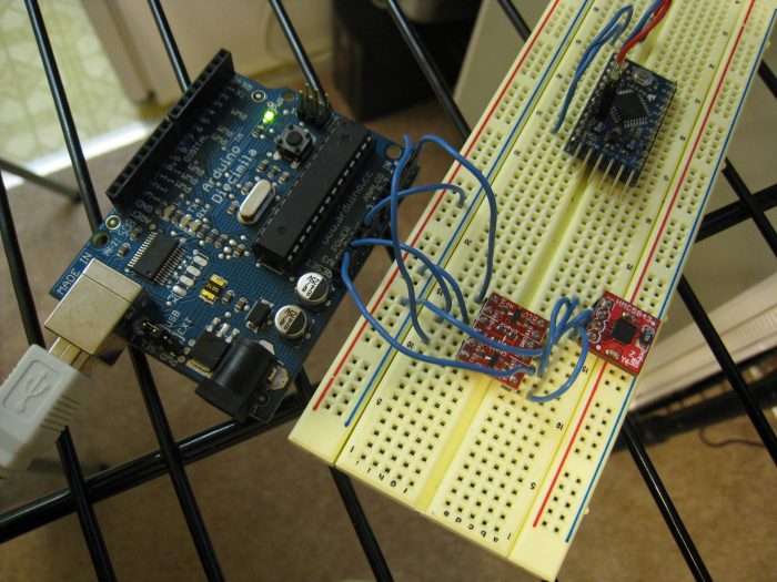
HMC5843 and Arduino

I (finally) have a project taking up the idle cycles of my brain, the first step of which involves figuring out how to use a magnetometer.  The project will eventually use the digital compass, accelerometers, perhaps a gyro, and maybe absolute forms of positioning like an IR camera.  I’m being slightly vague about this project both because the idea is by far the coolest thing I’ve ever come up with and because it is still somewhat short of half baked.

Anyway, Honeywell recently released a rather reasonably priced three axis magnetometer, the HMC5843, which SparkFun carries a breakout board for.  It interfaces over i2c, which is conveniently supported in hardware by most AVR microcontrollers, including the ones used on Arduino.  Arduino is something of paradox.  On one hard, the hardware is so simple and easy to use, vastly cutting down on the amount of time I need to spend arranging parts on a breadboard.  On the other hand, computations that should take a few operations instead call long functions that get compiled into hundreds, and the IDE makes me want to stab a stick of RAM into my jugular.  Luckily, one can mitigate the downsides by using an external editor, communicating with cutecom/minicom, and using avr-libc instead of the Arduino libraries as much as possible.  Back to the project.

The actual circuit is fairly simple.  Analog pins 4 and 5 on the Arduino serve as i2c’s SDA and SDC lines, respectively.  I’m using a level shifter from SparkFun to get the Arduino’s 5v lines down to the 3.3v that the HMC5843 is looking for.  Note that one can skip this by using a 3.3v Arduino Pro.  The FTDI chip on the Arduino outputs 3.3v, which is brought out on the headers, allowing the level shifter and the magnetometer to be powered off the Arduino.

I tried using the Arduino Wire library for i2c communication, but had no luck.  Atmel made TWI, the i2c implementation on the AVR, fairly easy to use, so I read through the datasheet, looked at some examples, and wrote my own Arduino library specifically for the HMC5843.  The current implementation is absolutely alpha, but it seems to read the x, y, and z values at 10 Hz correctly.  Note that you probably can’t use this library at the same time as Wire or another i2c library, and that it also doesn’t support having multiple i2c devices connected.  Its sole purpose is interfacing the HMC5843.  Here is an example sketch using it:

#include <HMC.h>
 
void setup()
{
  Serial.begin(9600);
  delay(5); // The HMC5843 needs 5ms before it will communicate
  HMC.init();
}
 
void loop()
{
  int x,y,z;
  delay(100); // There will be new values every 100ms
  HMC.getValues(&x,&y,&z);
  Serial.print("x:");
  Serial.print(x);
  Serial.print(" y:");
  Serial.print(y);
  Serial.print(" z:");
  Serial.println(z);
}

Continuing the theme of a different license for each set of code I release, this library is under a two clause BSD style license.  Please feel free to try it out and give me feedback/suggestions/patches/pedantic advice/flames.

Download and extract into the hardware/libraries/ folder of your Arduino directory:
HMC.zip

44 Comments on HMC5843 Magnetometer Library for Arduino

XBee Enabled Arduino Based Wireless Multimeter

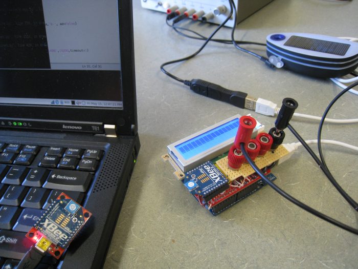
Multimeter

The title of this post is almost too thick with geeky goodness.  This past week, the ECE department at CMU held the kind of event I’ve been dreaming of for years: give a bunch of students free parts and access to labs and see what happens.  The event was called build_18 (sorry, no public site at the moment), and was the brainchild of Boris Lipchin.  There were some pretty amazing projects, like a laser guided Nerf chain gun.

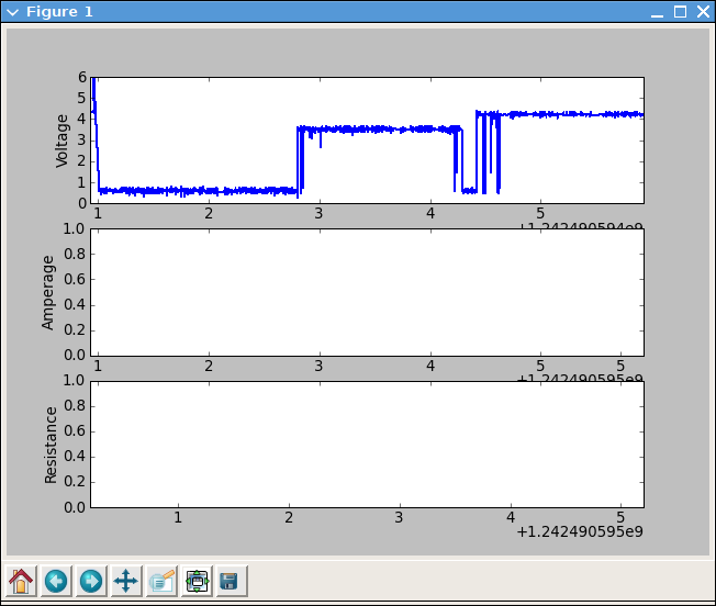
My roommate, Donald Cober, and I were planning on bringing back an old idea we never finished, a multimeter glove.  We decided that wasn’t difficult enough though, and added the killer feature of being able to stream data back to a computer for logging and display.  We had XBees left from the Wand project, so a serial point to point link using them was the logical choice.  We planned to read DC voltage, current, resistance, and temperature, and be autoranging on the first three.  Due to finals and catching up on a semester of missed sleep, we didn’t start the project until the morning before build_18 ended, so we had to drop the glove, ignore the onboard LCD (scavenged from an HP Laserjet), and focus on just getting voltage right.  Donnie had planned to build a Lithium Polymer battery board for Arduino, but we ended up having to power it off of Solio solar chargers that we won at a Yahoo University Hack Day last semester.  The multimeter itself is basically just a quad op amp, a few resistor networks, and some zener diodes sitting on an Arduino protoboard shield plugged into an Arduino Diecimila.  It actually worked quite nicely.  It is accurate from about -20 to 20 V and samples at about 2000 Hz, enough to see a nice sine wave on 60 Hz AC.

Multimeter plot

We are planning on finishing the other three data lines and getting the LCD working, so I will post again later with working schematics and an Arduino sketch.  I’m not going to leave you with nothing though.  The plotting app on the computer end is reasonably complete.  We used matplotlib with threading to avoid losing data.  It is fairly specific to our hardware, but it can at least serve as an example of how to do real time plotting in python.

Download: Multimeter Real Time Plotting Front End

1 Comment on XBee Enabled Arduino Based Wireless Multimeter

Magic Wands: ZigBee Enabled Group Gaming

Magic Wands

Over the last semester, my 18-549 group of Adeola Bannis, Claire Mitchell, Ethan Goldblum, and I has designed and prototyped a magic wand for theme park patrons to use for group games while waiting in long lines.  The initial idea of a crowd interaction device (and several thousand dollars of funding) was provided by Disney Research, but we ran with the concept, adding ZigBee wireless networking, an accelerometer, IR tracking via webcam, location based gaming, and so on.  We also wrote a few proof of concept games to go along with it.  I lost more sleep over this class than any other I’ve taken, but I learned quite a bit more as well.

The hardware is based loosely on Arduino, and we used their bootloader.  The software is a modified xbee-api-on-arduino library and code to interface the hardware.  The wand consists of an ATmega168, a 3-axis analog accelerometer, a Series 2 XBee, power and lithium ion charging circuitry, a 1400 mAh lithium ion battery, a very highly mediocre button pad, an RGB LED, an IR LED, and an incredible enclosure that Zach Ali at dFAB designed for us.  We went through a few hardware iterations before settling on this.  The prototypes we built are probably around $60 each in parts, but dropping the XBee for a basic 802.15.4 IC and buying in bulk would drop it below $20.  Our goal was to have the wand last a week long theme park visit without needing charged.  Our current implementation doesn’t put the XBee to sleep, so it would last around 24 hours of constant use.  Sleeping, we would reach about 9 days, surpassing the goal.  Swapping out the XBee would also cut current draw in half.  Wands can be charged over USB mini (yay for not using proprietary connectors!).

Perhaps the hardest part of the project was devising the network architecture and choosing where the divisions were between wand, server, and game.  In general, the underlying network is abstracted completely away from both the wands and the games.  The wands are simply advertised games that they are within range to play, and the games are sent joins when the wand joins the game.  There are wand and server side timers to make sure that wands are never stuck inside a game if someone walks out of range of the network.

The server tracks all joins and parts from games in a database, and there is a web based interface to allow for user tracking.  Perhaps my favorite simple gee-whiz feature that we added is remote battery level tracking.  Each time a wand joins a game, its battery level is logged, which is displayed in the web interface.  As the wands also have “display names” associated with them, it would be possible to tell someone, in game, that their battery level is low, if they ignore the red low battery LED on the wand.

The server is written in Java, using xbee-api to talk to wands and Google protobuf to serialize data to give to games.  We wrote client side networking libraries for Java and Python.  The games we wrote were mostly proof of concept to demonstrate the range of possible uses of the wand hardware.

The game below may look familiar.  I have stated probably multiple times that I would never touch RocketPong again, but it always manages to pull me back in.  In this variant, when a user joins the game, the star on their wand lights up with the color of their team, and their name appears next to their rocket.  They then tilt their wand up and down to control the thrust of the rocket.  The values between players on a team are averaged, so everyone on the team needs to cooperate if they want to win.  It ended up being a lot of fun, and was probably the most popular game during our final demo.  You can’t tell in the image below, but the star field in the background reacts to and collides with the ball, using the Lepton particle physics engine.

Group RocketPong

I also wrote a drawing game that uses the IR LED and a PS3 Eye modded with an IR filter.  We had originally used floppy disks for the filter, but we eventually got the correct IR bandpass filter for our LEDs.  I am really pleased with the PS3 Eye.  It is the only webcam I’ve seen that can do 60 fps VGA in Linux, and it also works beautifully with Pygame’s camera module.  The game is just a basic virtual whiteboard, allowing people to use their wand as a marker.  Pressing the buttons on the wand changes the color being drawn.  The whiteboard slowly fades away to white, erasing old drawings as the line moves on.  I had hoped to allow for multiple people to draw at the same time, but ran out of time.

During our final all-nighter, I quickly wrote a music app using the new Pygame midi module.  On joining the game, a user selects one of five instruments.  For the two percussion instruments, the user can shake the wand like a maraca or hit like a drumstick, using the accelerometer to trigger sound.  The other three instruments use the button pad to play notes.  Just because I could, this game also uses Lepton to shoot off music notes every time someone plays one.  This game is a really watered down version of a project called Cacophony that I will be developing farther when I have time.

We also had a trivia/voting game, and a cave game clone, which I did not write.

I doubt the project as a whole would be useful to anyone else out there, but individual chunks of it surely are.  You can get code, schematics, documentation, and assorted other junk for the entire project at our gitorious repo.  Note that parts of it probably don’t function, and much of it requires a very specific set of libraries.  If you are really interested, I would be happy to help you use what you want of it.  The licensing of just about everything is pretty murky, so talk to me first if you are planning on publishing anything based on this.

3 Comments on Magic Wands: ZigBee Enabled Group Gaming