Sometimes a project is just not meant to be. I picked up a Boogie Board LCD Writing Tablet when they went on sale to satiate my gadget addiction. I didn’t expect it to be hackable, as it is little more than a glorified chalkboard, but I figured I’d give it a try. My goal was to be able to lighten what was drawn on the screen, rather than erase it completely, to allow for the possibility of greyscale, or greenscale in this case.
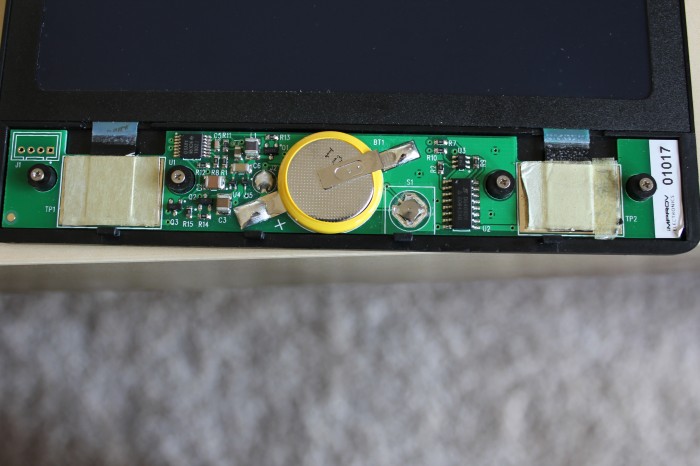
I cracked it open (literally, I didn’t realize there were screws under the sticker), and found a more complex machine than I expected. The brains of the tablet are an MSP430F2001, one of the cheaper microcontrollers in TI’s MSP430 lineup. The header on the left hooks up to the programming pins, so anyone out there with a GoodFET might want to take a look at writing new firmware for it. Unfortunately, I didn’t have one.
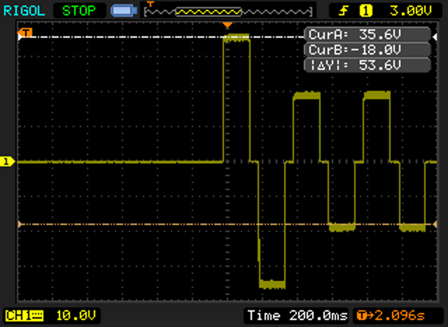
The waveform below captured between the two big pads, TP1 and TP2, shows how the cholesteric LCD refreshes. On pressing the button, the power circuitry on the left generates 36v for 400ms, followed by 18v for 800ms, and feeds it to the multiplexer on the right. The MSP430 toggles the input pins on the mux to switch that input voltage back and forth between the two pads in 150ms pulses, flashing the screen green and black and clearing what was drawn on it.
Unfortunately, while lifting the PCB up to see the traces on the bottom, I snapped one of the connections to the LCD, rendering the tablet useless. Hopefully someone can pick up where I left off, modify the firmware on the MSP430, and see if its possible to make the LCD go only partway cleared by using shorter or fewer pulses.


Have you heard of any successful attempts to hack the boogie board?
Nope.
What type/model of battery is that?
Been there man. Sorry.
Probably a CR2032 with tabs on…
Would it be possible to save your writing and sketches, if some external memory could be attached?
It doesn’t have a touch screen. This type of display gets lighter when u push on it. It only uses electricity to clear it. No memory, no input. I would LOVE to see one of these screens hooked to a PIC micro TBH.
MSP430F20x1
Five Power-Saving Modes
Internal Frequencies up to 16 MHz With Four Calibrated Frequencies to ±1%
Does the battery look like it can easily be replaced
Is the cr2032 battery have the metal tabs solder to it? Or can u pop out the battery easily?
I believe those tabs were spot welded to the cell.
Just opened mine up, have a launchpad, so i’m going to see if the JTAG emulator on the launchpad will work with this chip. If it does, I will get the firmware and decompile, hopefully getting some info on how this thing works, since mine seems to have cut out the multiplexer for what looks like a few transistors.
I verified it works with bi-spy-wire. The pinout of the header is:
TDI TST RST GND
you can hook up the last 3 to a launchpad and run mspdebug. I’m working on getting the firmware off it (should be easy as mine is a MSP430G2111, with 1kb flash).
Were you able to successfully obtain the firmware?
Can the lcd be repurposed with a matching lcd driver? And power supply
Just a thought… could we extract data from the internal antenna, run the signal to arduino, then bluetooth that to a tablet device or smartphone. Hence, we can utilize boogie board note taking feature and review our notes on our device more readily.
Anyone able to dump the firmware off it?
For anyone who needs to replace the battery on one these, it took me roughly 5 minutes. Here are the steps…
1. Unscrew the 4 screws found on the back of the tablet head (Screws are silver)
2. Pop open the face cover where the “Erase” button is found, there should be 4 small plastic clips on the back that clips it into place. Just pry them gently apart and it should pop out. You will then notice that the battery is wrapped in yellow tape with 2 soldered/welded clips found on each side of the battery.
3. The battery needed on mine was a CR 2025 (These do not have clips nor any soldering/welding, the battery is sold naked. However the battery in the boogie board tablet IS soldered onto the clips attached to the tablet.) “How do you take the battery out if the clips have been soldered/welded onto the battery?” EASY, take a small flat head screw driver and work it with a jerking motion in between the clips and the battery to separate them. It took me about 10 secs for each clip.
4. After you’ve removed the battery from the clips, you will notice that the clips are most likely and almost inevitably trashed…right? Yes but we can fix that! Grab your useful Flat Nose Head Plier and ‘plier’ back into shape (flat/straight).
5. Place the battery in between the clips with the rough side up and place the face cover back into place, clip it in and screw the screws back into place. This is what I did and the battery stayed in place. You can also use tape or glue to further strengthen the battery in place but I found it unnecessary.
Good luck!
Thank you so much for this I will save it for when mine dies.
Hey CP, just wanted to let you know I followed your steps and it worked like a charm. I didn’t have to solder anything and it still works. the odd thing is the erase button wasn’t working but when I pried the connectors off and reinserted the old battery it worked! maybe something had come loose? Anyway I have a spare CR2025 on hand when this battery dies. This was an Xmas gift that was Dead On Arrival and I am not the most handy of folks either! Thanks so much!
Hi. I bought the pink plastic boogie board for my daughter 4yr ago. And the battery ran out like 2yr ago. What I did just now after reading your post is I peeled out the top sticker with a cutter carefully cutting the double tape and then took out the 4 tiny screws. I also pried the weldedbattery tabs on top and on the bottom and replace it with a cr2025 panasonic button batt. I used hot glue applied on the negative non contact side to keep it stuck to th PCB and then applied a dab of hot glue on the top part to keep it in place with the cover. It works.thanks for your post.
Five Power-Saving Modes
Internal Frequencies up to 16 MHz With Four Calibrated Frequencies to ±1%.
Would it be possible to save your writing and sketches, if some external memory could be attached?