What “Hardware is Hard” Really Means

I was chatting with a new hardware entrepreneur recently who asked an excellent question: What does “Hardware is hard” really mean?  It being time consuming and expensive to iterate on, not being able to ship patches, requiring specialized skillsets, and having access to a smaller pool of investors are all reasons commonly mentioned.  These all relate, but at its core, what makes hardware hard is that you don’t get second chances.

Pick the wrong audience target, go to market strategy, feature set, pricing, production forecast, manufacturing methodology, manufacturing partners, or logistics partners, and you will run out of money.  Worse, you can get all but one of those things right and still never make it off the ground.  Startups require setting a bold hypothesis and then charting a narrow course to proving it.  In many software and service businesses, you can set short milestones to test and iterate with target audiences closed-loop, course correcting rapidly to find product market fit with a small team before scaling.  If you have a strong team and you’re picking good hypotheses, you’ll have a reasonable chance to get enough funding to keep going at it for some time.

With hardware, each of those is orders of magnitude more challenging.  Iteration cycles are expensive, partner and technology selections can take you through one way doors you can’t afford to walk back from, and building inventory of the wrong product or for the wrong audience is fatal.  Perhaps most critically, if you run out of money, you are unlikely to get funding to pivot, no matter how strong your team is.

All of that said, hardware is essential to civilization and a whole lot of fun to make.  Nobody needs another Web3 NFT marketplace.  Build something that matters.  Here’s what you can do to minimize your likelihood of death along the way:

  1. Be extremely deliberate about your audience sequencing.  Think about the first 1k, the first 10k, the first 100k, and the first 1M customers.  Don’t start your company with a product or go to market strategy for the first 1M customers unless you are certain that it is what will also satisfy the first 1k.  It takes brand awareness, company credibility, and ultimately the right product to fit your audiences’ needs to reach each subsequent level of scale.  There are ways to streamline this that will depend on your product and category.  For example, starting with an openly available development kit works well for products that will eventually have a hardware or software ecosystem attached to them (something we did successfully at Oculus).
  2. Deeply understand how your audiences behave today, what they are buying, and why what you are building would be enough better to make them change their behavior.  Think through the purchase cycle.  Does this need to be a replacement, a first product, a second product, or a toy to tinker with?  I don’t generally subscribe to product/management fads, but Jobs-to-be-done has a useful framing for audience psychology with the “four forces” diagram.
  3. Build the right team and pick the right partners.  Many hardware startups try to emulate Apple’s product and design philosophy and then replicate the staffing model that requires.  Don’t.  Start with the smallest possible team for what you need to differentiate on in design and engineering along with the core set of people needed to safely steer supply chain and logistics.  Leverage partners for everything else.  You can always in-house more in the future as you scale, but don’t make the mistake of building substantial capital infrastructure or hiring team members that you don’t need to to reach product market fit.  You can solve this with a competent manufacturing partner that has expertise or at least transferable skills and infrastructure for your space. You can work with them in a “Joint Development Model”.  The people you’ll work with there will be carrying in an enormous amount of collective experience and team cohesion, won’t need equity, can move fast, and will generally require less OpEx than hiring the equivalent capability in house.
  4. Think carefully about funding and runway.  Unless you can afford to self-fund your company to profitability, make sure you’re actively having discussions with potential investors as you plan, whether angels or institutional VCs.  Lay out your hypotheses around product roadmap and audience scaling and the funding milestones that go with them.  Critically, make sure plausible investors agree that those are sensible milestones, otherwise you’ll end up at one without the cash to go further.
  5. Find ways to get the first 1k or 10k customers to help fund the business.  Never use equity to fund inventory.  Think carefully about how you can generate enough credibility to get 1k or 10k people to put money down on a product that hasn’t been manufactured yet.  That is most often in the form of pre-orders.  Credibility generation may be through seeding development units to influential users or press in the space, though a limited developer kit program, through a community beta program, or other creative paths.  If you can’t get 1k customers to take the bet and spend money on your product, investors probably shouldn’t place a bet on you either.

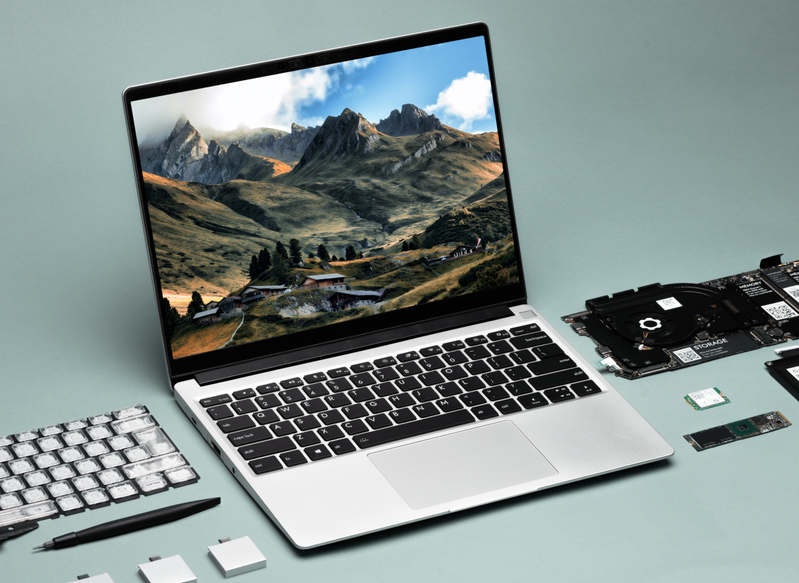
This is by no means a comprehensive list of tactics, but a condensed set of viewpoints around a topic that could fill a book.  Note that all of the numbers above assume a consumer hardware product in a large category.  Feel free to scale the numbers appropriately for enterprise/commercial/niche hardware.  If you’re starting a hardware startup, especially in consumer, and you’d like feedback on how you’re approaching it, feel free to send me an email.  I applied each of the above to Framework, and would be happy to help check for startup-advice-fit on other companies.

2 Comments on What “Hardware is Hard” Really Means

Parametric M.2 Mockup Generator

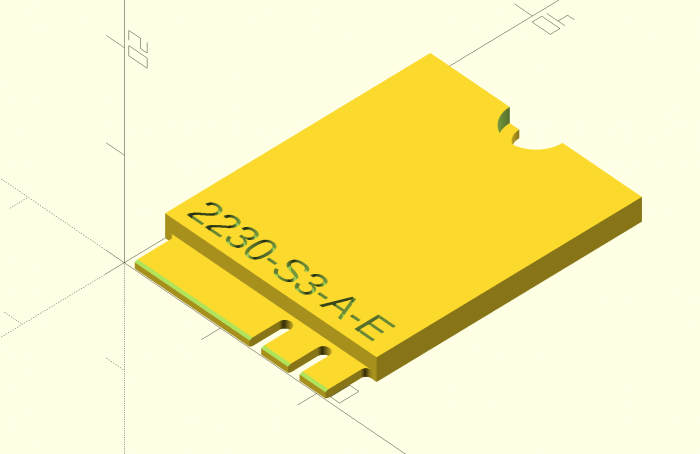
The thing I’m sharing today is a very early and very small slice of the project that is likely going to consume the next few years of my life. This is a parametric generator for M.2 expansion card mockups in OpenSCAD.

I can’t imagine this is useful to many people, but the beauty of open source software and hardware is that it doesn’t have to be. Even if only one person happens upon this years down the road and it saves them a few hours or gives them the reference point they needed, it was worth sharing. Sharing knowledge isn’t zero-sum; it’s exponential (though maybe not in this specific instance).

// M.2 Mockup Generator
// by Nirav Patel <https://eclecti.cc>
//
// To the extent possible under law, Nirav Patel has waived all copyright
// and related or neighboring rights to M.2 Mockup Generator.
//
// An easy to use parametric M.2 mockup generator.
// See https://en.wikipedia.org/wiki/M.2 for more information about the 
// M.2 (formerly NGFF) standard.

edge_width = 19.85;
edge_length = 4;
edge_r = 0.5;
hole_r = 1.75;
key_r = 0.6;
key_length = 3.5;

pcb_thick = 0.8;
bottom_edge_keepout = 5.2;
top_gnd_pad_r = 2.75;
bottom_gnd_pad_r = 3;
bottom_gnd_pad_offset = 1;
bevel = 0.3;
bevel_angle = 20;

$fn=50;

module key_cutout() {
    union() {
        translate([0, key_length - key_r]) circle(r = key_r);
        translate([-key_r, -1]) square([key_r*2,key_length - key_r +1]);
    }
}

function get_key(key_type="mm") =
    key_table[search([key_type],key_table,1,0)[0]][1];

key_table = [["", 100], ["A", 6.625], ["B", 5.625], ["C", 4.625], ["D", 3.625], ["E", 2.625], ["F", 1.625], ["G", -1.125], ["H", -2.125], ["J", -3.125], ["K", -4.125], ["L", -5.125], ["M", -6.125]];

module m2_2d(width=22, length=30, key="M", key2="") {
    // Start with a 2d version
    difference() {
        square([width, length]);
        
        // Left cutout
        translate([(width-edge_width)/2-width, -edge_r]) square([width, edge_length]);
        translate([(width-edge_width)/2-width-edge_r, 0]) square([width, edge_length]);
        translate([(width-edge_width)/2-edge_r, edge_length-edge_r]) circle(r=edge_r);
        
        // Right cutout
        translate([width-(width-edge_width)/2, -edge_r]) square([width, edge_length]);
        translate([width-(width-edge_width)/2+edge_r, 0]) square([width, edge_length]);
        translate([width-(width-edge_width)/2+edge_r, edge_length-edge_r]) circle(r=edge_r);
        
        // Hole cutout
        translate([width/2, length]) circle(r = hole_r);
        
        // Key cutouts
        translate([width/2 + get_key(key), 0])
            key_cutout();
        
        translate([width/2 + get_key(key2), 0])
            key_cutout();
    }
}

module m2_text(width=22, length=30, height="", key="", key2="") {
    if (key2 != "") {
        string = str(width, length, "-", height, "-", key, "-", key2);
        linear_extrude(height = 1)
            text(string, size = 2.5);
    } else {
        string = str(width, length, "-", height, "-", key);
        linear_extrude(height = 1)
            text(string, size = 2.5);
    }
}

module m2(width=22, length=30, height="", key="", key2="") {
    union() {
        difference() {
            linear_extrude(height = pcb_thick)
                m2_2d(width, length, key, key2);
            
            // The card edge bevel
            translate([0, bevel, 0]) rotate([180-bevel_angle, 0, 0]) cube([width, 10, 10]);
            translate([0, bevel, pcb_thick]) rotate([90+bevel_angle, 0, 0]) cube([width, 10, 10]);
        }
        
        difference() {
            // The various component keepout zones and embossed text
            if (height == "S1") {
                difference() {
                    translate([0, edge_length, pcb_thick]) cube([width, length-edge_length, 1.2]);
                    translate([1, edge_length+1, pcb_thick+1.2-0.5]) m2_text(width, length, height, key, key2);
                }
            } else if (height == "S2") {
                difference() {
                    translate([0, edge_length, pcb_thick]) cube([width, length-edge_length, 1.35]);
                    translate([1, edge_length+1, pcb_thick+1.35-0.5]) m2_text(width, length, height, key, key2);
                }
            } else if (height == "S3") {
                difference() {
                    translate([0, edge_length, pcb_thick]) cube([width, length-edge_length, 1.5]);
                    translate([1, edge_length+1, pcb_thick+1.5-0.5]) m2_text(width, length, height, key, key2);
                }
            } else if (height == "D1") {
                difference() {
                    translate([0, edge_length, pcb_thick]) cube([width, length-edge_length, 1.2]);
                    translate([1, edge_length+1, pcb_thick+1.2-0.5]) m2_text(width, length, height, key, key2);
                }
                translate([0, bottom_edge_keepout, -1.35]) cube([width, length-bottom_edge_keepout, 1.35]);
            } else if (height == "D2") {
                difference() {
                    translate([0, edge_length, pcb_thick]) cube([width, length-edge_length, 1.35]);
                    translate([1, edge_length+1, pcb_thick+1.35-0.5]) m2_text(width, length, height, key, key2);
                }
                translate([0, bottom_edge_keepout, -1.35]) cube([width, length-bottom_edge_keepout, 1.35]);
            } else if (height == "D3") {
                difference() {
                    translate([0, edge_length, pcb_thick]) cube([width, length-edge_length, 1.5]);
                    translate([1, edge_length+1, pcb_thick+1.5-0.5]) m2_text(width, length, height, key, key2);
                }
                translate([0, bottom_edge_keepout, -1.35]) cube([width, length-bottom_edge_keepout, 1.35]);
            } else if (height == "D4") {
                difference() {
                    translate([0, edge_length, pcb_thick]) cube([width, length-edge_length, 1.5]);
                    translate([1, edge_length+1, pcb_thick+1.5-0.5]) m2_text(width, length, height, key, key2);
                }
                translate([0, bottom_edge_keepout, -0.7]) cube([width, length-bottom_edge_keepout, 0.7]);
            } else if (height == "D5") {
                difference() {
                    translate([0, edge_length, pcb_thick]) cube([width, length-edge_length, 1.5]);
                    translate([1, edge_length+1, pcb_thick+1.5-0.5]) m2_text(width, length, height, key, key2);
                }
                translate([0, bottom_edge_keepout, -1.5]) cube([width, length-bottom_edge_keepout, 1.5]);
            } else {
                translate([1, edge_length+1, pcb_thick-0.5]) m2_text(width, length, height, key, key2);
            }
            
            // The ground pad keepouts
            translate([width/2, length, pcb_thick]) cylinder(r = top_gnd_pad_r, h = 10);
            translate([width/2, length-bottom_gnd_pad_offset, -10]) {
                cylinder(r = bottom_gnd_pad_r, h = 10);
                translate([-bottom_gnd_pad_r, 0, 0]) cube([bottom_gnd_pad_r*2, bottom_gnd_pad_offset, 10]);
            }
        }
    }
}

m2(width=22, length=30, height="S3", key="A", key2="E");

This is also up on GitHub as a Gist.

No Comments on Parametric M.2 Mockup Generator

Fully Parametric 3D Printable Computer Case

Modeled in OpenSCAD
When looking into small form factor cases to build a Mini-ITX PC for my Rift, I found a few things:

  1. Like any other hobby, there is an obsessive (in a good way) community of small form factor enthusiasts.
  2. The metric they optimize for is case size in liters.
  3. Often, people are stuck sub-optimally limiting their component selection to the case they want or their case selection to fit the components they have.

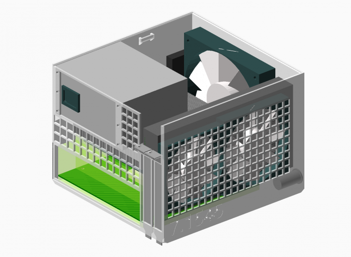
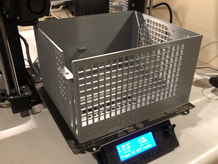
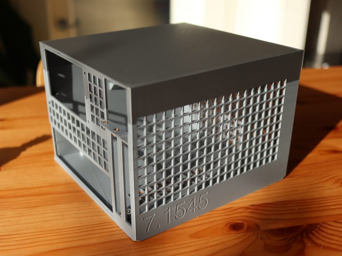
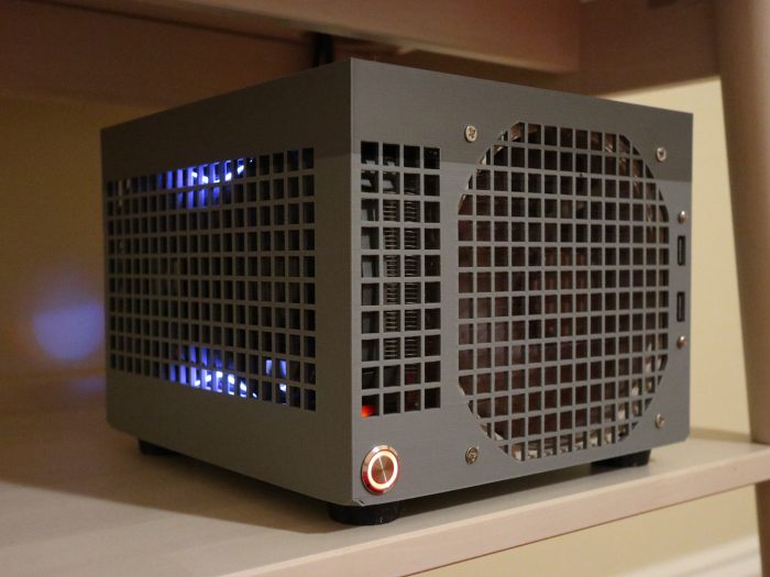
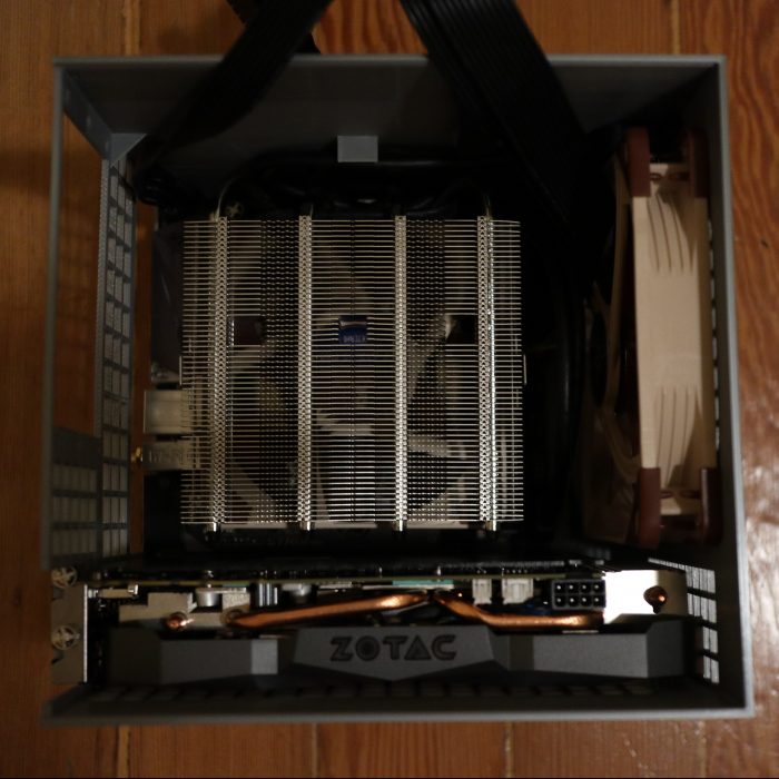
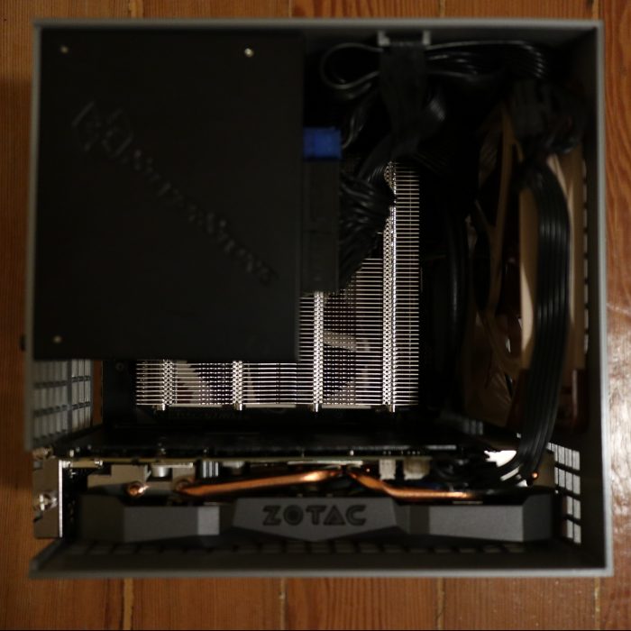
Rather than limiting choice or ending up with a larger than desired case, why not make your case exactly match the size of the components you want with no wasted space?  It turns out that a Mini-ITX motherboard, SFX power supply, and short GPU just barely fit within the bounds of a Prusa i3 MK3 3D printer, so I decided to solve exactly that with an open source fully parametric printable case in OpenSCAD.  That means you can input the components you have or edit a few dimensions and output a bespoke case that fits them perfectly.  To win community brownie points, the volume of the case is also automatically generated and embossed on the side.

Just barely fits.
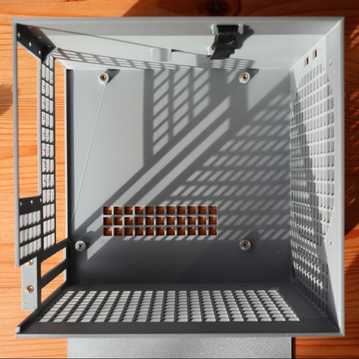
Partly for rigidity and partly for simplicity of design and assembly, I decided to make it effectively a bucket with most of the case being a single print. I started with a traditional “shoebox” layout to keep it simple as well. The only other parts are the lid and optional feet (printable in flexible material like TPU). I also used threaded inserts rather than screwing into plastic to allow re-assembly without destroying the case.

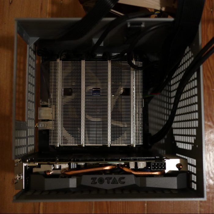
I referenced the Mini-ITX and PCI-e specs to get the proper dimensions, and measured the components I had on hand and pulled some datasheets online for specifics on heatsinks and the GPU. There is pretty good ventilation all around, with the default configuration that fits my components having a 140mm intake fan and a mostly isolated GPU with dedicated intake and exhaust.

Un-intentionally two-tone.
It took me three or four iterations of prints (~36 hours and ~400g/$8 of plastic each) to get to a level of completeness that I’m happy with using and publishing, but there is certainly more to improve.  Since it is open source, revisions and fixes are welcome.

I tried to make it as simple as possible to customize by having keyword fields for the power supply type and heatsink chosen. The PSU can be SFX, SFX-L, or FlexATX, and heatsink can be a 120mm AIO, Noctua NH-L12s, Noctua NH-U9s, or Cryorig C7. If you have any of those and the same GPU I have (Zotac 1080 Mini), you can just edit the keywords and the case will be automatically generated to fit them. If you want to make deeper changes or use different components, you can do so by editing the .scad files.

traditional(show_body = true, show_lid = false, show_internals = false, heatsink_type = "noctua_nh_l12s", psu_type = "sfx");

The two-tone is unintentional. I ran out of filament partway through.
The full CAD, example ready-to-print .stl files, and instructions are up on GitHub, licensed under an Open Source 2-Clause BSD license.  You can also follow along the development thread at SFF Forum.

6 Comments on Fully Parametric 3D Printable Computer Case

Revisiting RepRap 8 years later with a Prusa i3 MK3

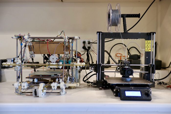
You can see the resemblance.
It’s remarkable how much and how little has changed with RepRap since I built a Mendel in late 2010.  The basic architecture has proven incredibly robust.  The most popular home 3D printers including the Prusa i3 MK3 that I bought still use an open frame with a moving bed on a belt for Y, moving extruder on a belt for X, dual driven lead screws for Z, gear driven filament into a hot end with a heat break and heat block, a 0.4mm nozzle, and an ATmega2560 for control.  I suspect if I dug into the firmware, I’d even find some source in common between the Prusa firmware on the MK3 and Sprinter firmware I used on the Mendel.

The seal of excellence.
That may sound like criticism, but I actually mean it as praise.  Over the last 8 years, there have been hundreds of diverging and converging iterations on the Mendel formula enabled by its open source nature, with each fixing flaws and adding improvements over the last.  It took me about two months of research to get the right parts and another two months of building and tuning to get my old Mendel to print anything at all, and it took a stack of hacks and modifications of mechanical design, circuitry, firmware, and host software that meant I was probably the only person who could speak the incantations required to operate the thing.  With the MK3, it took 4-5 hours of assembly (by choice; you can order it pre-assembled) and absolutely no configuration to get to a perfect first print, and there are thousands of people with the same configuration.

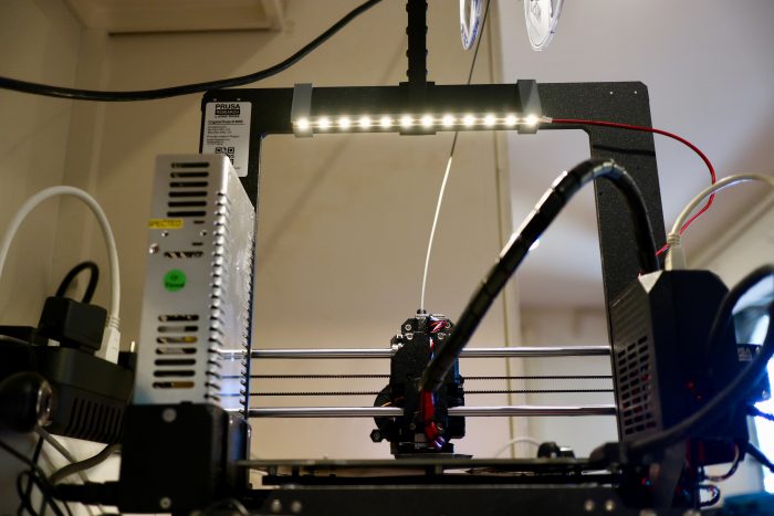
It's hard to take a picture of a light.
The printer isn’t perfect, but again open source comes to the rescue.  I had taken a few months hiatus using a Monoprice Mini Delta 3D Printer, and while it was a nice tool, it had a range of bugs and irritating flaws that were challenging or impossible to correct.  With the Prusa, I found that I needed a light to provide illumination for the webcam attached to the OctoPrint Raspberry Pi driving it.  I was able to pull up the schematic and rig up an LED strip trivially.  I’ve posted up the CAD and instructions on Thingiverse so anyone else with an MK3 or derived printer can do it too!

No Comments on Revisiting RepRap 8 years later with a Prusa i3 MK3

Tiny USB Type C Adjustable Power Supply

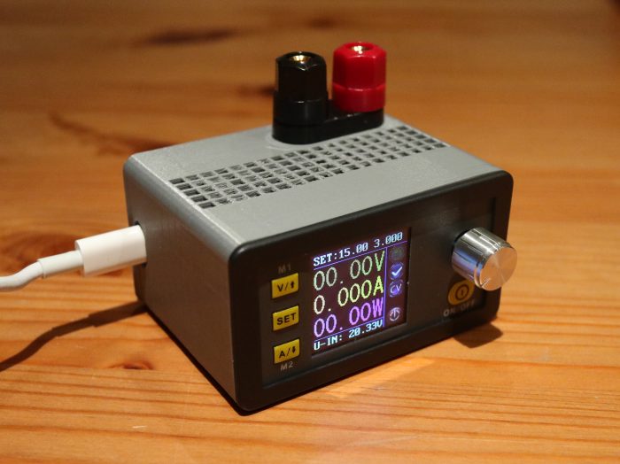
Tiny Power Supply
When building projects professionally, I try to take every shortcut possible to accelerate learnings around an idea and get useful results to inform the next iteration. When building projects personally, I do basically the opposite. Often when starting with an idea, I’ll find that it would be helpful to build a tool to execute on the idea cleanly, so I switch tracks to building the tool. Sometimes, when trying to build that tool, I’ll find that I’m missing some other tool and build that instead. This is one of those.

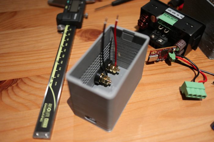
The guts
I couldn’t find an adjustable power supply in my house (I think my personal one became property of Oculus at some point), and I couldn’t find a small simple one that I liked online, so I built the one I wanted. This is just a 3d printed housing with a PD Buddy USB Type C board, a Rui Deng DPS5005 Switching Power Supply, and banana plug terminals inside. It supports around 0-19V output from a 20V Type C power supply like a MacBook Pro charger and up to 5A. Rui Deng’s DPS3005 would technically also be sufficient if you want to save a few bucks. The result is a cute little adjustable desktop power supply that solves for what most of my projects need. The OpenSCAD and STL files along with assembly instructions are on Thingiverse.

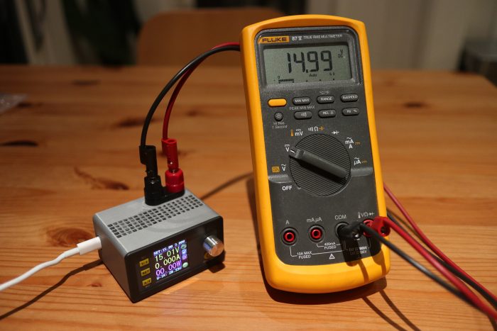
Not the world's most accurate power supply.

3 Comments on Tiny USB Type C Adjustable Power Supply

Snow Globe Redux: Gakken Worldeye Projector Upgrade

Worldeye projector upgrade

A few month hiatus from this blog turned into five and a half years, but that is a much longer story.  This one is about the state of desktop spherical displays in 2018.  In 2011, I hacked together the Snow Globe spherical display from a laser pico-projector, an off the shelf fish-eye lens, a bathroom light fixture, and some shader code.  I had hoped to make it easy for folks to build their own version by publishing everything, but the lens ended up being unobtanium.  Judging by the comments on the post, nobody was able to properly replicate the build.

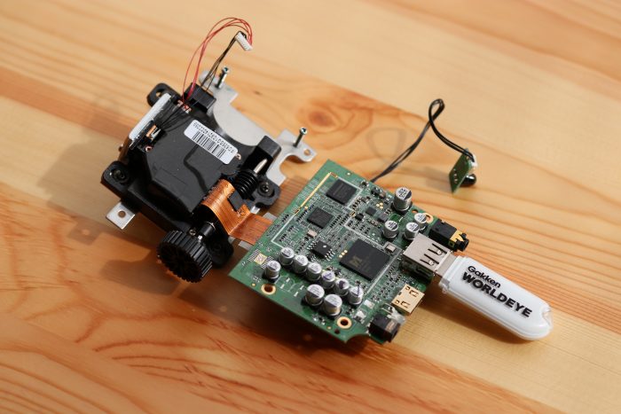
Gakken Worldeye Teardown

A few months ago Palmer Luckey gave me heads up that a company called Gakken in Japan had a consumer version of the idea and that like everything in the world, there were sellers on eBay and Amazon importing it into the US.  The Gakken Worldeye sounded like it could fulfill the dream of a desktop spherical display, so I bought one to use and another to tear down.  It ended up being a hemispherical display with a pretty decent projection surface but a terrible projector and even worse driving electronics.  The guts of the sphere are above.  There is a VGA resolution TI DLP that is cropped by the lens to a 480 pixel circle.  The Worldeye takes 720p input over HDMI, which is then downsampled and squashed horizontally to that circle by an MStar video bridge.  Between the poor projector resolution and the questionable resampling, the results look extremely blurry.

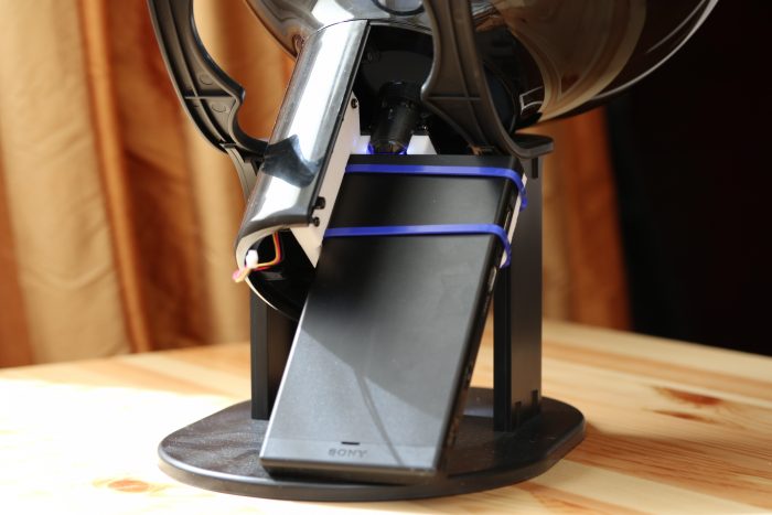
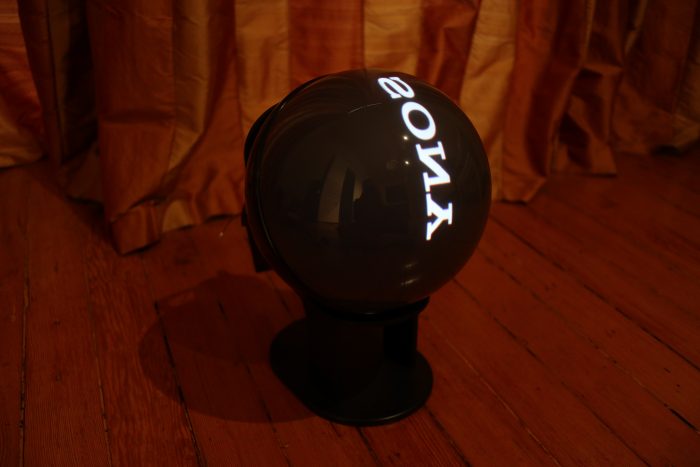
Sony spherical projector

I figured it would be possible to improve on the sphere by taking advantage of the display surface and lens and swapping out the projector and electronics.  In the time since the ShowWX used in the Snow Globe was released, Microvision has developed higher resolution laser scanning projector modules in conjunction with Sony and others.  I picked up a Sony MP-CL1 with one of these modules, which is natively 1280×720.  This should have been a decent improvement over the 848×480 in the ShowWX.  I then CAD’d up and 3d printed a holder to mount it along with the original Worldeye lens into the globe.

Higher resolution Gakken Worldeye

The results are a bit underwhelming.  The image looks better than the stock Worldeye, but still looks quite blurry.  I realized afterwards that the sphere diameter is too small to take advantage of the projector resolution.  At around a 5″ radius, the surface of the sphere is getting around 1.8 pixels per mm (assuming uniform distortion).  The laser beam coming out of the projector is well over 1 mm wide, and probably closer to 1.5mm.  This means that neighboring pixels are blending heavily into each other.  The lens MTF is probably also pretty poor, which doesn’t help the sharpness issue.  If you’re interested in trying this out anyway, the .scad and .stl files are up on Thingiverse and the code for the Science on a Snow Globe application to display equirectangular images and videos is on GitHub.  The conclusion to the opening prompt is that spherical displays are more accessible in 2018 than they were in 2011, but don’t seem to be any better quality.  Hopefully someone takes the initiative to solve this.

16 Comments on Snow Globe Redux: Gakken Worldeye Projector Upgrade