Fully Parametric 3D Printable Computer Case

Modeled in OpenSCAD
When looking into small form factor cases to build a Mini-ITX PC for my Rift, I found a few things:

  1. Like any other hobby, there is an obsessive (in a good way) community of small form factor enthusiasts.
  2. The metric they optimize for is case size in liters.
  3. Often, people are stuck sub-optimally limiting their component selection to the case they want or their case selection to fit the components they have.

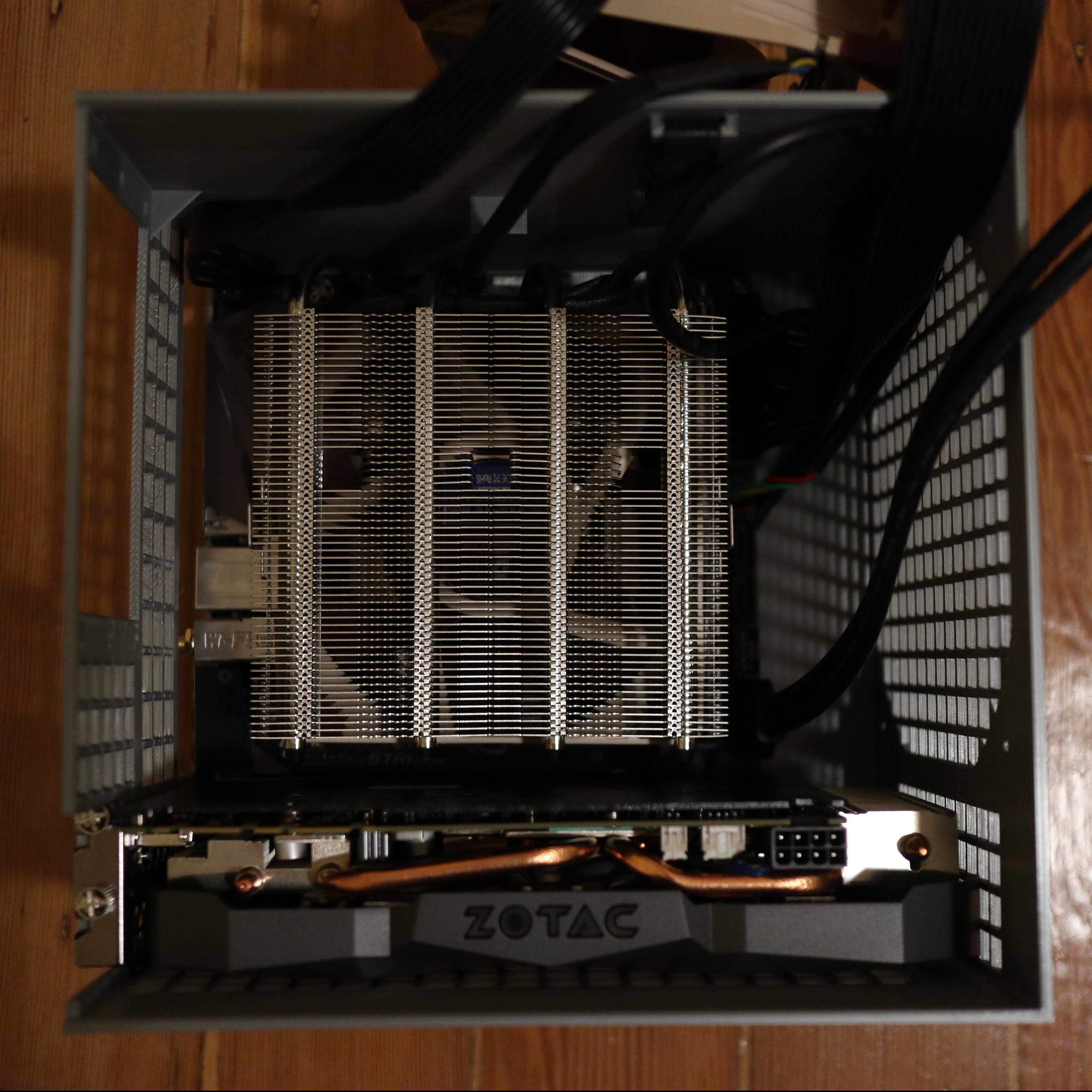
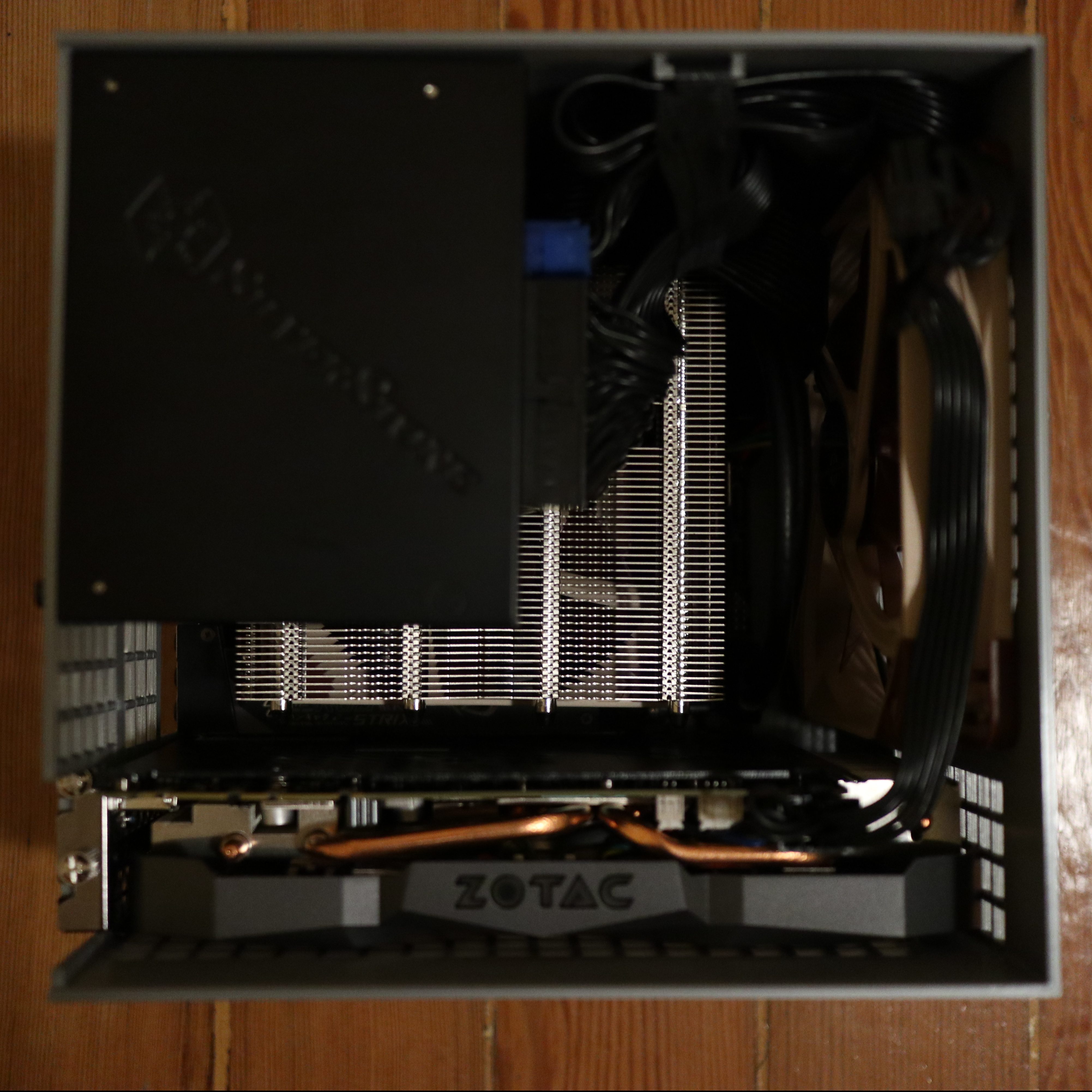
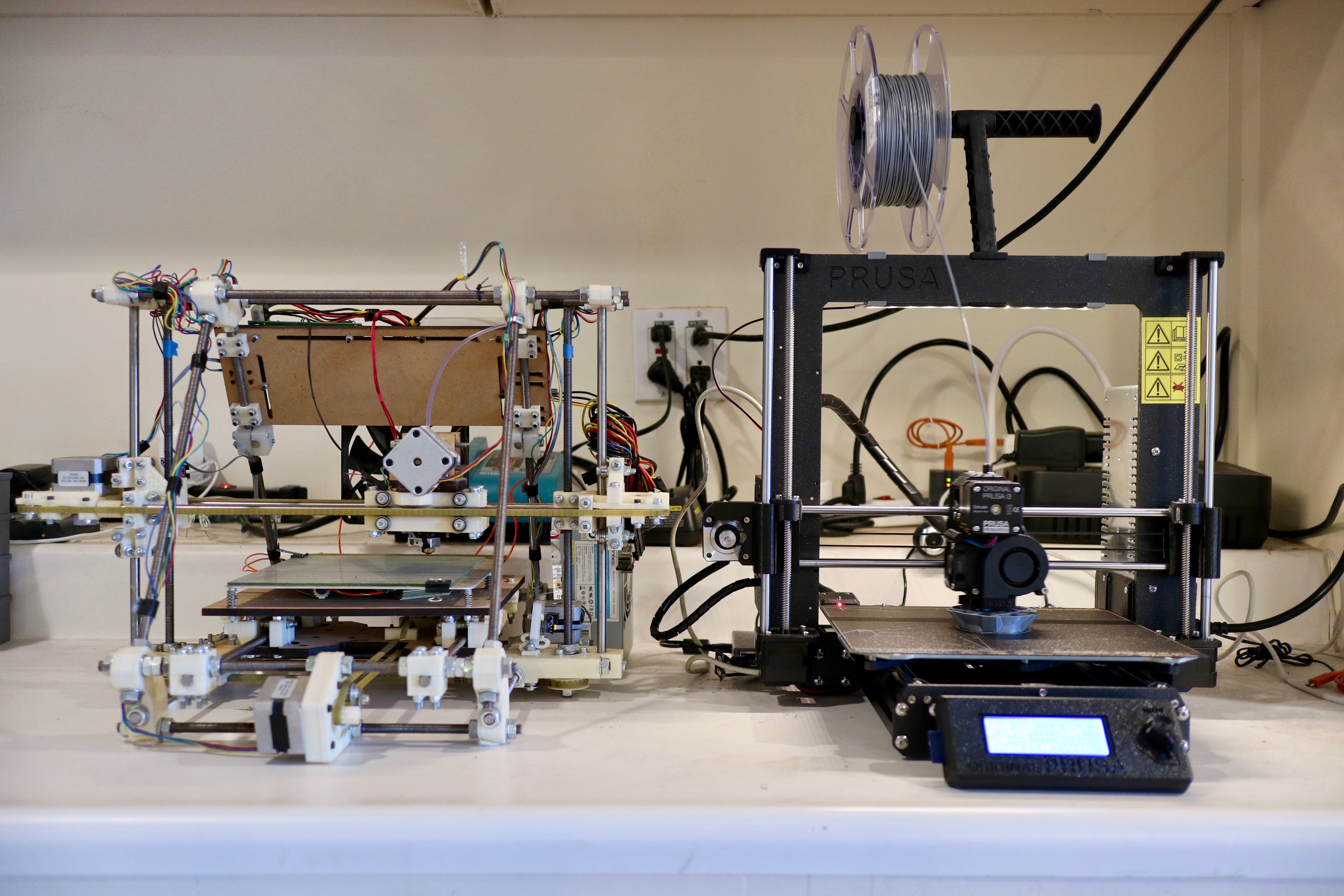
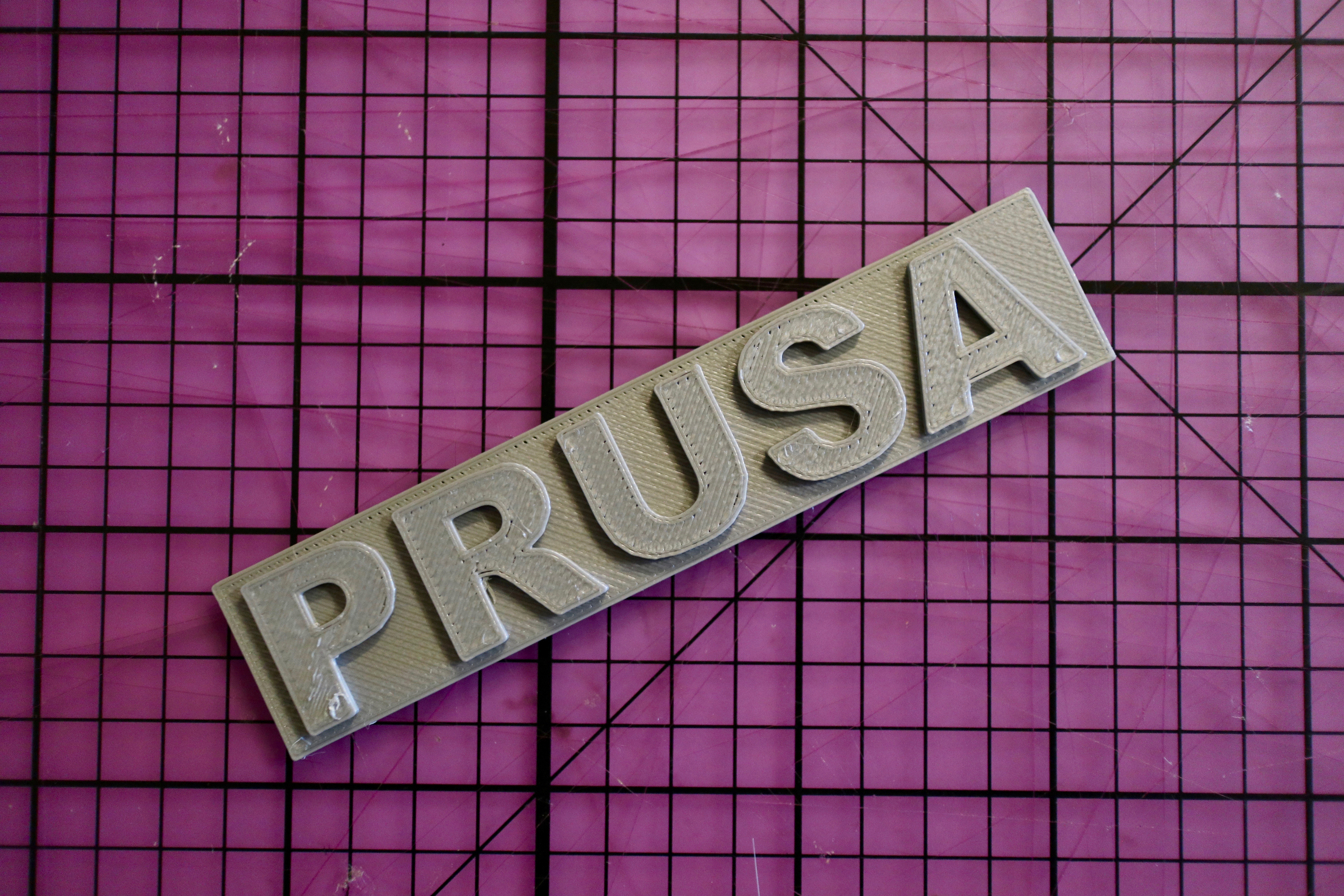
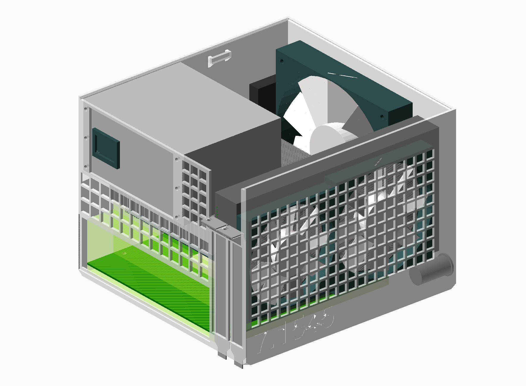
Rather than limiting choice or ending up with a larger than desired case, why not make your case exactly match the size of the components you want with no wasted space?  It turns out that a Mini-ITX motherboard, SFX power supply, and short GPU just barely fit within the bounds of a Prusa i3 MK3 3D printer, so I decided to solve exactly that with an open source fully parametric printable case in OpenSCAD.  That means you can input the components you have or edit a few dimensions and output a bespoke case that fits them perfectly.  To win community brownie points, the volume of the case is also automatically generated and embossed on the side.

Just barely fits.
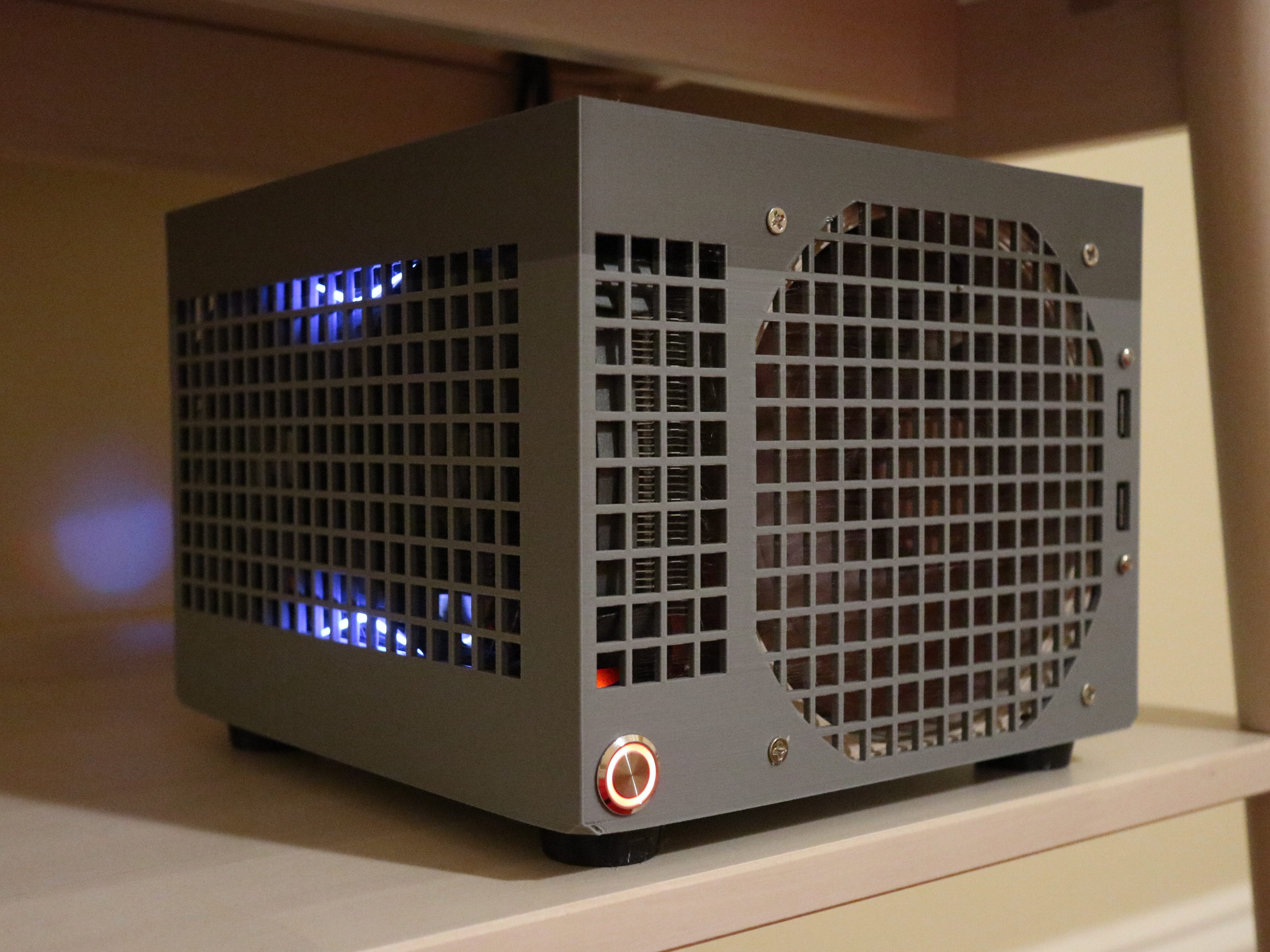
Partly for rigidity and partly for simplicity of design and assembly, I decided to make it effectively a bucket with most of the case being a single print. I started with a traditional “shoebox” layout to keep it simple as well. The only other parts are the lid and optional feet (printable in flexible material like TPU). I also used threaded inserts rather than screwing into plastic to allow re-assembly without destroying the case.

I referenced the Mini-ITX and PCI-e specs to get the proper dimensions, and measured the components I had on hand and pulled some datasheets online for specifics on heatsinks and the GPU. There is pretty good ventilation all around, with the default configuration that fits my components having a 140mm intake fan and a mostly isolated GPU with dedicated intake and exhaust.

Un-intentionally two-tone.
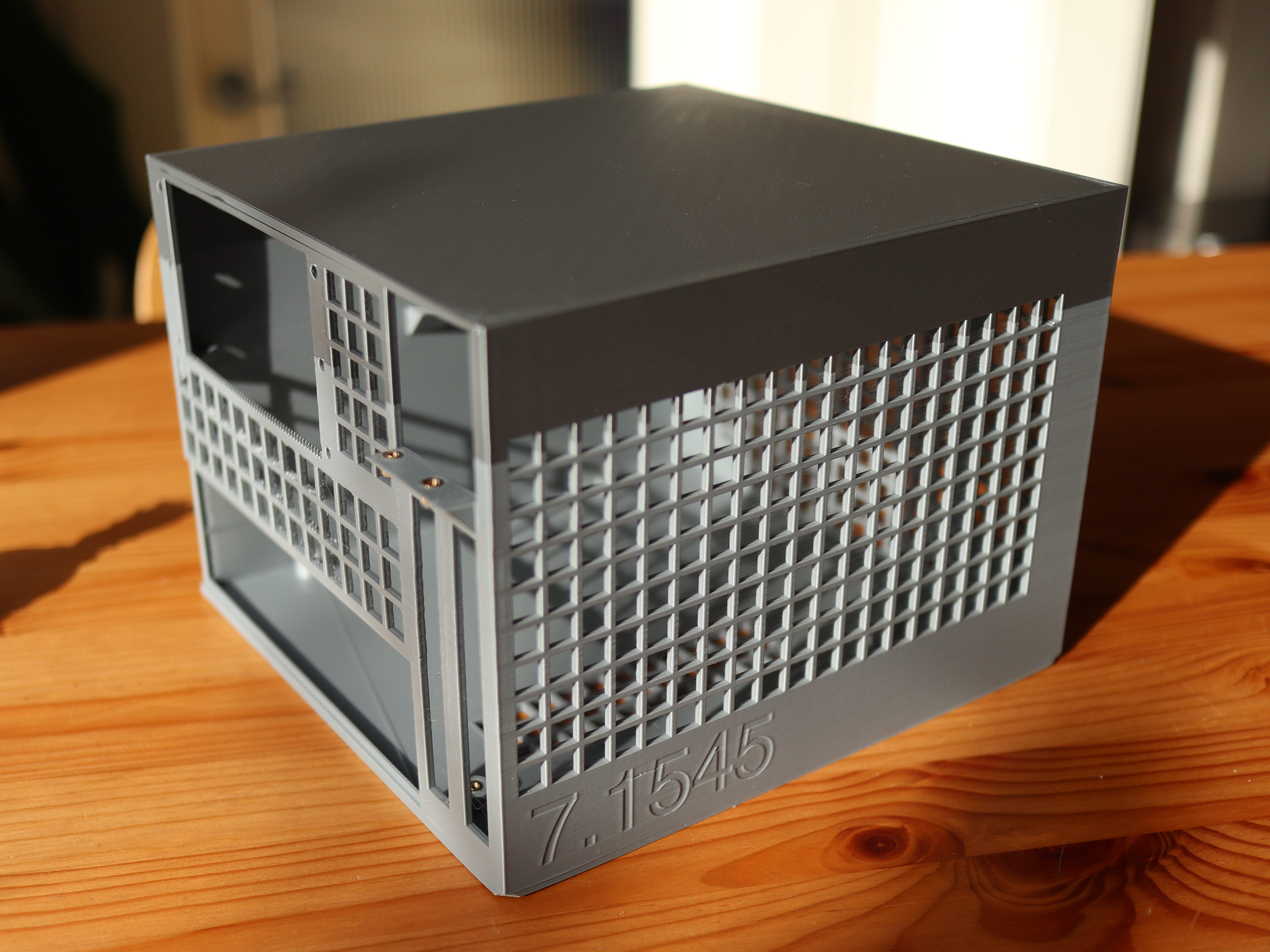
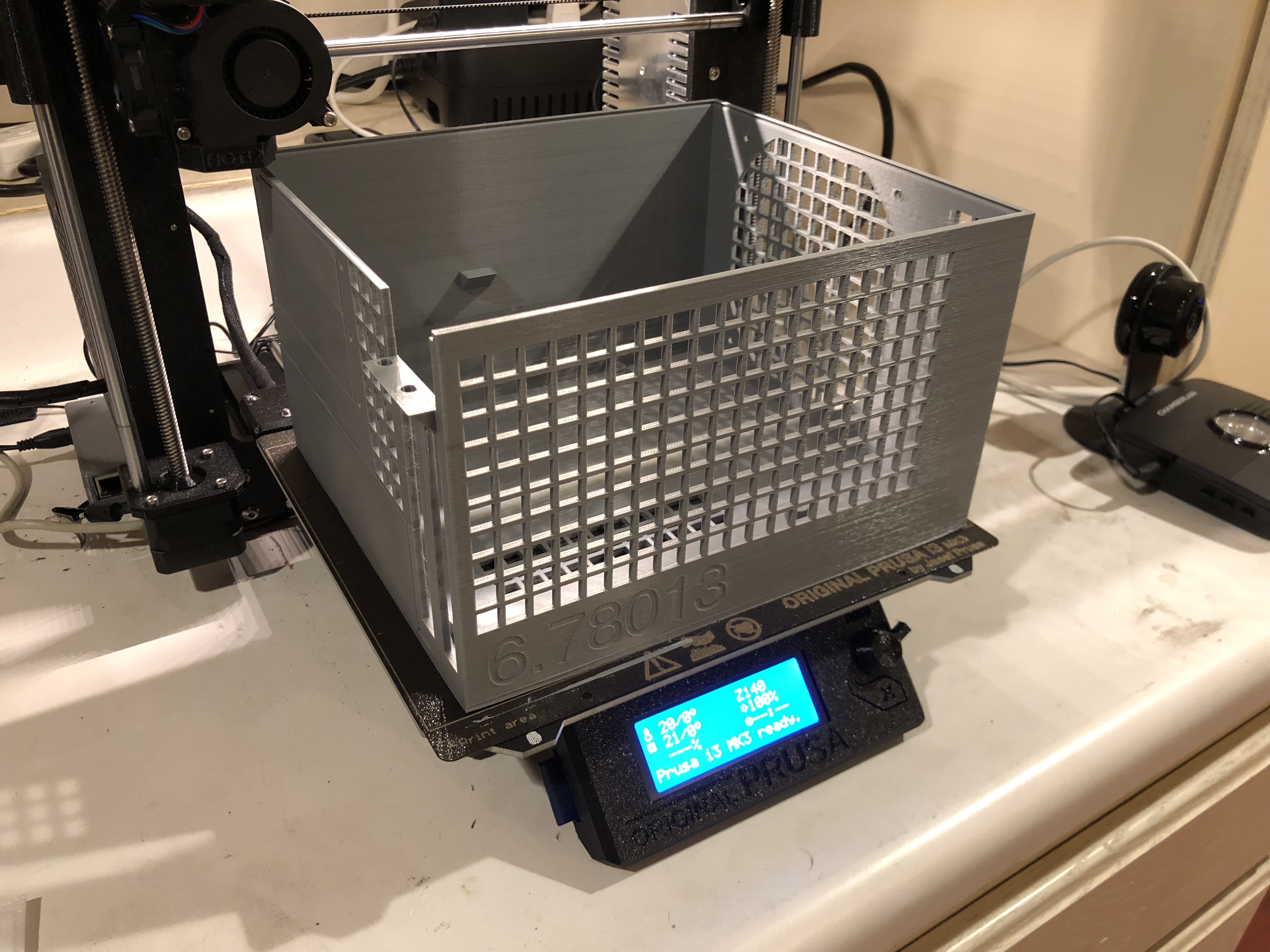
It took me three or four iterations of prints (~36 hours and ~400g/$8 of plastic each) to get to a level of completeness that I’m happy with using and publishing, but there is certainly more to improve.  Since it is open source, revisions and fixes are welcome.

I tried to make it as simple as possible to customize by having keyword fields for the power supply type and heatsink chosen. The PSU can be SFX, SFX-L, or FlexATX, and heatsink can be a 120mm AIO, Noctua NH-L12s, Noctua NH-U9s, or Cryorig C7. If you have any of those and the same GPU I have (Zotac 1080 Mini), you can just edit the keywords and the case will be automatically generated to fit them. If you want to make deeper changes or use different components, you can do so by editing the .scad files.

traditional(show_body = true, show_lid = false, show_internals = false, heatsink_type = "noctua_nh_l12s", psu_type = "sfx");

The two-tone is unintentional. I ran out of filament partway through.
The full CAD, example ready-to-print .stl files, and instructions are up on GitHub, licensed under an Open Source 2-Clause BSD license.  You can also follow along the development thread at SFF Forum.

7 Comments on Fully Parametric 3D Printable Computer Case

Revisiting RepRap 8 years later with a Prusa i3 MK3

You can see the resemblance.
It’s remarkable how much and how little has changed with RepRap since I built a Mendel in late 2010.  The basic architecture has proven incredibly robust.  The most popular home 3D printers including the Prusa i3 MK3 that I bought still use an open frame with a moving bed on a belt for Y, moving extruder on a belt for X, dual driven lead screws for Z, gear driven filament into a hot end with a heat break and heat block, a 0.4mm nozzle, and an ATmega2560 for control.  I suspect if I dug into the firmware, I’d even find some source in common between the Prusa firmware on the MK3 and Sprinter firmware I used on the Mendel.

The seal of excellence.
That may sound like criticism, but I actually mean it as praise.  Over the last 8 years, there have been hundreds of diverging and converging iterations on the Mendel formula enabled by its open source nature, with each fixing flaws and adding improvements over the last.  It took me about two months of research to get the right parts and another two months of building and tuning to get my old Mendel to print anything at all, and it took a stack of hacks and modifications of mechanical design, circuitry, firmware, and host software that meant I was probably the only person who could speak the incantations required to operate the thing.  With the MK3, it took 4-5 hours of assembly (by choice; you can order it pre-assembled) and absolutely no configuration to get to a perfect first print, and there are thousands of people with the same configuration.

It's hard to take a picture of a light.
The printer isn’t perfect, but again open source comes to the rescue.  I had taken a few months hiatus using a Monoprice Mini Delta 3D Printer, and while it was a nice tool, it had a range of bugs and irritating flaws that were challenging or impossible to correct.  With the Prusa, I found that I needed a light to provide illumination for the webcam attached to the OctoPrint Raspberry Pi driving it.  I was able to pull up the schematic and rig up an LED strip trivially.  I’ve posted up the CAD and instructions on Thingiverse so anyone else with an MK3 or derived printer can do it too!

1 Comment on Revisiting RepRap 8 years later with a Prusa i3 MK3

Tiny USB Type C Adjustable Power Supply

Tiny Power Supply
When building projects professionally, I try to take every shortcut possible to accelerate learnings around an idea and get useful results to inform the next iteration. When building projects personally, I do basically the opposite. Often when starting with an idea, I’ll find that it would be helpful to build a tool to execute on the idea cleanly, so I switch tracks to building the tool. Sometimes, when trying to build that tool, I’ll find that I’m missing some other tool and build that instead. This is one of those.

The guts
I couldn’t find an adjustable power supply in my house (I think my personal one became property of Oculus at some point), and I couldn’t find a small simple one that I liked online, so I built the one I wanted. This is just a 3d printed housing with a PD Buddy USB Type C board, a Rui Deng DPS5005 Switching Power Supply, and banana plug terminals inside. It supports around 0-19V output from a 20V Type C power supply like a MacBook Pro charger and up to 5A. Rui Deng’s DPS3005 would technically also be sufficient if you want to save a few bucks. The result is a cute little adjustable desktop power supply that solves for what most of my projects need. The OpenSCAD and STL files along with assembly instructions are on Thingiverse.

Not the world's most accurate power supply.

1 Comment on Tiny USB Type C Adjustable Power Supply

Blinded by the Light: DIY Retinal Projection

Retinal Projection

After grabbing a couple of Microvision SHOWWX laser picoprojectors when they went up on Woot a few months back, I started looking for ways to use them.  Microvision started out of a project at the University of Washington HITLab in 1994 to develop laser based virtual retinal displays.  That is, a display that projects an image directly onto the user’s retina.  This allows for a potentially very compact see through display that is only visible by the user.  The system they developed reflected lasers off of a mechanical resonant scanner to deflect them vertically and horizontally, placing pixels at the right locations to form an image.  The lasers were modulated to vary the brightness of the pixels.  The SHOWWX is essentially this setup after 15 years of development to make it inexpensive and miniaturize it to pocket size.  The rest of the retinal display system was a set of optics designed to reduce the scanned image down to a point at the user’s pupil.  I thought I would try to shrink and cheapen that part of it as well.

The setup I built is basically what Michael Tidwell describes in his Virtual Retinal Displays thesis.  The projected image passes through a beamsplitter where some of the light is reflected away, reflects off of a spherical concave mirror to reduce back down to a point, and hits the other side of the beamsplitter, where some of the light passes through and the rest is reflected to the user’s pupil along with light passing through the splitter from the outside world.  For the sake of cost savings, all of my mirrors are from the bargain bin of Anchor Optics.  The key to the project is picking the right size and focal length of the spherical mirror.  The larger setup in the picture below uses a 57mm focal length mirror, which results in a fairly large rig with the laser scanner sitting at twice the focal length (the center of curvature) away from the mirror.  The smaller setup has a focal length around 27mm, which results in an image that is too close to focus on unless I take my contact lenses out.  The mirror also has to be large enough to cover most of the projected image, which means the radius should be at least ~0.4x the focal length for the 24.3° height and at most ~0.8x for the 43.2° width coming from a SHOWWX.  Note that this also puts the field of view of the virtual image entering the eye somewhere between a 24.3° diameter circle and a 24.3° by 43.2° rounded rectangle.

Projection Rig

Aside from my inability to find properly shaped mirrors, the big weakness of this rig is the size of the exit pupil.  The exit pupil is basically the useful size of the image leaving the system.  In this case, it is the width of the point that hits the user’s pupil.  If the point is too small, eye movement will cause eye pupil to miss the image entirely.  Because the projector is at the center of curvature of the mirror (see the optical invariant), the exit pupil is the same the width as the laser beams coming out of the projector: around 1.5 mm wide.  This makes it completely impractical to use head mounted or really, any other way.  I paused work on this project a few months ago with the intention of coming back to it when I could think of a way around this.  With usable see through consumer head mounted displays just around the bend though, I figured it was time to abandon the project and publish the mistakes I’ve made in case it helps anyone else.

If you do want to build something like this, keep in mind that the title of this post is only half joking.  I don’t normally use bold, but this is extra important: If you don’t significantly reduce the intensity of light coming from the projector, you will damage your eyes, possibly permanently.  The HITLab system had a maximum laser power output of around 2 μW.  The SHOWWX has a maximum of 200mW, which is 100,000x as much!  Some folks at the HITLab published a paper on retinal display safety and determined that the maximum permissible exposure from a long term laser display source is around 150 μW, so I needed to reduce the power by at least 10,000x to have a reasonable safety margin.  As you can see in the picture above, I glued a ND1024 neutral density filter over the exit of the projector, which reduces the output to 0.1%.  Additionally, the beamsplitter I picked reflects away 10% of the light after it exits the projector, and 90% of what bounces off of the concave mirror.  Between the ND filter, the beamsplitter, and setting the projector to its lowest brightness setting, the system should be safe to use.  The STL file and a fairly ugly parametric OpenSCAD file for the 3D printed rig to hold it all together are below.

blinded.scad
blinded.stl

17 Comments on Blinded by the Light: DIY Retinal Projection

Augmented Reality for 3D Printing

Yoda
My roommate’s struggles designing his first 3D printed part gave me the idea to write an augmented reality viewer that lets you preview and interact with STL models in the real world without having to commit an object to plastic. This is actually sort of an update on part of a project I did for a Computational Photography course three years ago, but not terrible looking this time. I used the ArUco library to track the fiducial markers, largely because there is a javascript version if I ever want to make it web based. The program, which I uncreatively named arstl, reads in ASCII and binary STL files and displays them on top of the tracked marker. Right now, it uses a pretty basic OpenGL shader for a shiny plastic look, but I plan on making a more convincingly plastic one with bump mapping and subsurface scattering soon. As usual, the code is up on github under an ISC License. The STL parsing part of it is in the public domain, in case anyone finds it useful.

2 Comments on Augmented Reality for 3D Printing

Thingidiff: Visualizing 3D Model Diffs with Thingiview.js

Thingidiff

Thingiverse is an enormous resource for mostly open source, ready to print 3D objects.  It conveniently has both a built in understanding of derivative objects and a web based 3D object viewer.  It has no mechanism for combining the two though, making comparing any two objects a matter of either visual guesswork or downloading and comparing the files against each other.

Thingidiff is my fork of Thingiview.js allowing for web based visual comparisons between related 3D objects.  Colors and opacities can be set for faces that are the same in both objects or unique to one or the other.  The obvious use cases for this are showing a diff between a derived object and its original or showing differences in revisions of a work in progress.  Both of these cases are in evidence on the example page.  Note that between this being my first project in Three.js or Javascript at all and the currently mercurial state of WebGL support in web browsers, there are probably going to be nits, bugs, or even outright computer exploding failures in your experience.  I’m interested in bug reports though, if you would be willing to drop them on the github project’s Issues page.  The code itself is nearby.

1 Comment on Thingidiff: Visualizing 3D Model Diffs with Thingiview.js

RepRap Controlled Time-Lapse Photography

While capturing the time-lapse last week, John and I ran into two irritating issues.  The first is that the moving platform causes the object being printed to come in and out of the focal plane of the camera and makes for a jarring video.  The second is that because the interval between photos is constant, some large and slow layers will have multiple shots taken while several consecutive quick layers can be skipped entirely.  The solution to both of these is to dynamically remote trigger the camera from the printer.

I wrote a Skeinforge photograph plugin that inserts a new G-code command, M240, which tells the printer to trigger a photograph.  The module offers three modes.  End of Layer, as demonstrated by Yoda above, is the simplest.  It takes one picture at the start of the first layer and then another at the end of each layer of the print, resolving only the second of the aforementioned issues.  Corner of Layer takes a picture at the minimum Y,X of each layer.  Least Change between Layers tries to take shots that are as close as possible to each other from layer to layer.  I had the most visually interesting results with the last setting, as shown in the Flower print up top.  The module can be downloaded from github, and installation instructions are included within its text.

Infrared Trigger

The other half of the control scheme is triggering the camera from the RepRap.  Since I didn’t want to risk coupling my T2i directly to the printer, I went for emulating a Canon RC-1 Remote, which has been thoroughly reverse engineered.  The hardware is simply an 850nm infrared LED in series with a 180 ohm resistor connected to one of the I/O pins on the Arduino Mega.  I chose pin 23 because I could solder to it without pulling my RAMPS board off.  The software side is equally simple.  For this, I forked the excellent Sprinter firmware to respond to M240 and send the correct pulse over the IR LED.  My fork is on github, but the diff that adds M240 support is the interesting bit.

3 Comments on RepRap Controlled Time-Lapse Photography

Time-Lapse of a RepRap Print

John visited recently and suggested that we bring another photographic production to the world: this time, a time-lapse of the RepRap printing out an interesting looking object.  After some frustrating attempts to install the Canon EOS Utility, we just used an intervalometer directly on my T2i with the Magic Lantern firmware.  In case you want to try it out and to save me a lot of Googling in the future, here are the mencoder parameters to generate a sanely sized video from high resolution stills.

mencoder -ovc lavc -lavcopts vcodec=mjpeg -mf fps=10:type=jpg -vf scale=960:720 'mf://*.JPG' -o timelapse.avi

Depending on which project gets swapped into my next free time slot, I may have another post soon exploring an extension on this that John and I discussed.

3 Comments on Time-Lapse of a RepRap Print

Snow Globe: Part One, Cheap DIY Spherical Projection

Earth in Snow Globe

Since reading Snow Crash, I’ve been drawn to the idea of having my own personal Earth.  Because I’m stuck in reality and the virtual version of it is always 5 years away, I’m building a physical artifact that approximates the idea: an interactive spherical display.  This is of course something that exists and can likely be found at your local science center.  The ones they use are typically 30-100″ in diameter and cost enough that they don’t have prices publicly listed.  Snow Globe is my 8″ diameter version that costs around $200 to build if you didn’t buy a Microvision SHOWWX for $600 when they launched like I did.

Lens mount

The basic design here is to shoot a picoprojector through a 180° fisheye lens into a frosted glass globe.  The projector is a SHOWWX since I already have one, but it likely works better than any of the non-laser alternatives since you avoid having to deal with keeping the surface of the sphere focused.  Microvision also publishes some useful specs, and if you ask nicely, they’ll email you a .STL model of their projector.  The lens is an Opteka fisheye designed to be attached to handheld camcorders.  It is by far the cheapest 180° lens I could find with a large enough opening to project through.  The globe, as in my last dome based project is for use on lighting fixtures.  This time I bought one from the local hardware store for $6 instead of taking the one in my bathroom.

I’ve had a lot of fun recently copying keys and people, but my objective in building a 3D printer was to make it easier to do projects like this one.  Designing a model in OpenSCAD, printing it, tweaking it, and repeating as necessary is much simpler than any other fabrication technique I’m capable of.  In this case, I printed a mount that attaches the lens to the correct spot in front of the projector at a 12.15° angle to center the projected image.  I also printed brackets to attach the globe to the lens/projector mount.  The whole thing is sitting on a GorillaPod until I get around to building something more permanent.

Snow Globe

Actually calibrating a projector with slight pincushion through a $25 lens into a bathroom fixture attached together with some guesswork and a 3D printer is well beyond my linear algebra skill, so I simplified the calibration procedure down to four terms.  We need to find the radius in pixels of the circle being projected and the x and y position of the center of that circle for starters.  The more difficult part, which tested my extremely rusty memory of trigonometry is figuring out how to map the hemisphere coming out of the fisheye lens to the spherical display surface.  For that, we have a single number for the distance from the center of the sphere to the lens, in terms of a ratio of the projected radius.  The math is all available in the code, but the calibration script I wrote is pretty simple to use.  It uses pygame to project longitude lines and latitude color sections as in the image above.  You use the arrow keys to line up the longitude lines correctly to arrive at the x and y position, plus and minus keys to adjust the radius size until it fits the full visible area of the sphere, and 9 and 0 to adjust the lens offset until the latitudes look properly aligned.  What you end up with is close enough to correct to look good, though as you can see in the images, the projector doesn’t quite fit the lens or fill the sphere.  The script saves the calibration information in a pickle file for use elsewhere.

Projected sphere

Going back to the initial goal, I wrote a script to turn equirectangular projected maps of the Earth into roughly azimuthal equidistant projected images calibrated for a Snow Globe like the one above.  There are plenty of maps of the former projection available freely, like Natural Earth and Blue Marble. Written in python, the script is quite slow, but it serves as a proof of concept.  The script, along with the calibration script and the models for the 3D printed mounts are all available on github.  I’ve finally fully accepted git and no longer see a point in attaching the files to these posts themselves.  I put a Part One in the title to warn you that this blog is going to be all Snow Globe all the time for the foreseeable future.  Up next is writing a faster interface to interactively display to it in real time, and if I think of a good way to do it, touch input is coming after that.

Download from github:
git://github.com/nrpatel/SnowGlobe.git

114 Comments on Snow Globe: Part One, Cheap DIY Spherical Projection