Evil Eye: Microvision SHOWWX as a Face Tracking Eyeball

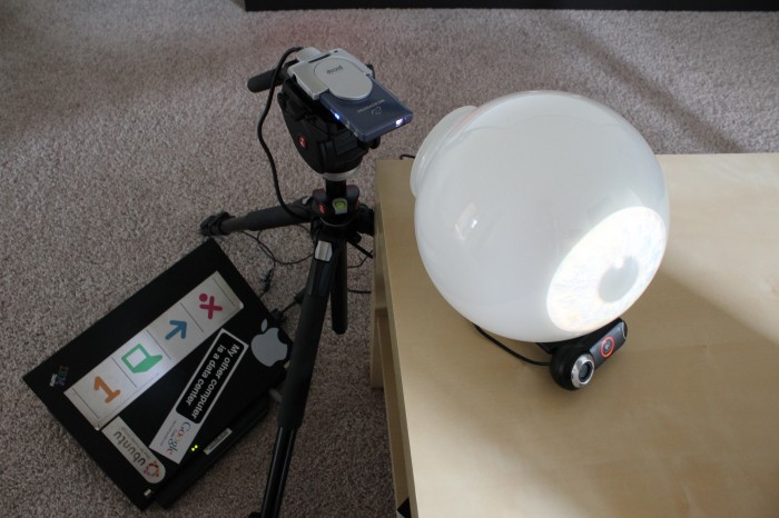
This idea, like most good ones, came to me while I was in my bathroom.  I recently took delivery of a Microvision SHOWWX laser pico projector, and I was trying to come up with a quick project to show the cool stuff it could do.  I noticed that the light above my mirror was diffused by a large frosted glass dome, which led to this strange project.  It’ll probably make more sense around Halloween.

Microvision SHOWWX Setup

The software is pretty similar to what I wrote the last time I did face tracking:  OpenCV’s very convenient Haar feature detection along with Pygame to do the image display.  I tried taking a picture of my own eye, but Flickr user Sarah Cartwright’s is much more photogenic and available under Creative Commons Attribution-Share Alike.

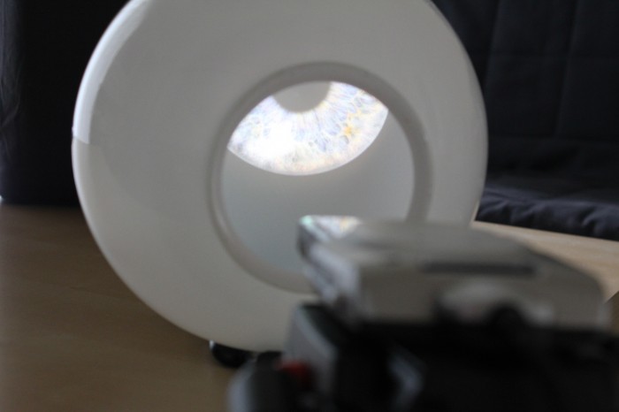
Inside the Eye

A regular pico projector would probably work as well, but the contrast ratio on this thing means it looks like the iris is being projected by itself.  I have some much cooler projects planned that will really take advantage of the focus free nature of the laser projector.  In the mean time, the code for this project is available below.  The image is CC A-SA, the code is public domain, and the Haar file is Intel License Agreement like the rest of OpenCV.  I also attached the Python script itself for perusal by search engines or folks who just want to see the code.

Download:
EvilEye.zip
EvilEye.py

8 Comments on Evil Eye: Microvision SHOWWX as a Face Tracking Eyeball

A Failed Hack: Boogie Board LCD Writing Tablet

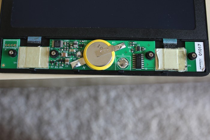
Boogie Board Internals

Sometimes a project is just not meant to be.  I picked up a Boogie Board LCD Writing Tablet when they went on sale to satiate my gadget addiction.  I didn’t expect it to be hackable, as it is little more than a glorified chalkboard, but I figured I’d give it a try.  My goal was to be able to lighten what was drawn on the screen, rather than erase it completely, to allow for the possibility of greyscale, or greenscale in this case.

I cracked it open (literally, I didn’t realize there were screws under the sticker), and found a more complex machine than I expected.  The brains of the tablet are an MSP430F2001, one of the cheaper microcontrollers in TI’s MSP430 lineup.  The header on the left hooks up to the programming pins, so anyone out there with a GoodFET might want to take a look at writing new firmware for it.  Unfortunately, I didn’t have one.

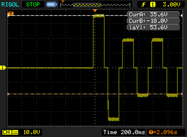
The waveform below captured between the two big pads, TP1 and TP2, shows how the cholesteric LCD refreshes.  On pressing the button, the power circuitry on the left generates 36v for 400ms, followed by 18v for 800ms, and feeds it to the multiplexer on the right.  The MSP430 toggles the input pins on the mux to switch that input voltage back and forth between the two pads in 150ms pulses, flashing the screen green and black and clearing what was drawn on it.

Boogie Board Waveform

Unfortunately, while lifting the PCB up to see the traces on the bottom, I snapped one of the connections to the LCD, rendering the tablet useless.  Hopefully someone can pick up where I left off, modify the firmware on the MSP430, and see if its possible to make the LCD go only partway cleared by using shorter or fewer pulses.

91 Comments on A Failed Hack: Boogie Board LCD Writing Tablet

Walk This Way: Pedestrian Traffic Light Status Indicator

Traffic Sign Status Indicator

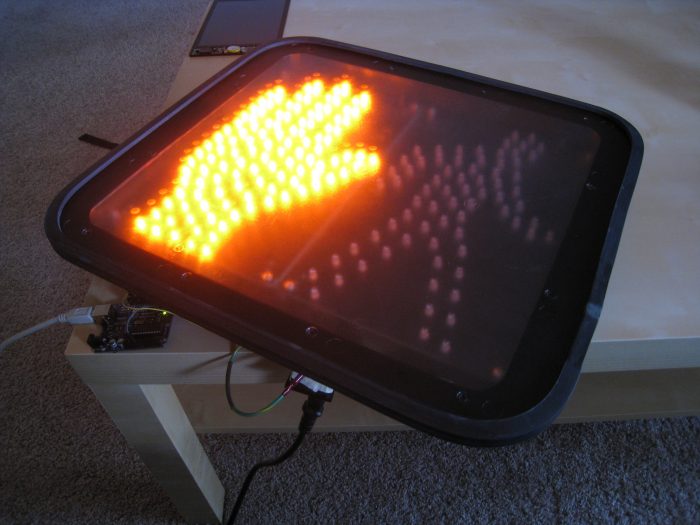
A recent Slashdot post about Weird Stuff Warehouse reminded me that they carry cheap pedestrian traffic lights. I’d been meaning to pick one up to use as a completely overkill status indicator at work.  I managed to get this one for $10. It is a GE PS7-CFC1-01A that uses LEDs and looks new, but was presumably dumped by the original owner because it is a basic stop/go light without a countdown timer or accessibility features.

Dual Power Supplies

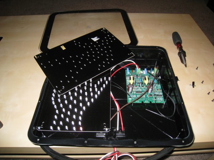
There were three mystery wires coming out of the back to interface it, so I cracked it open to see what was inside. The stop hand and walk person have independent AC-DC power supplies. Both halves share the white neutral wire, while each has a live wire of its own. The idea is to have the common line always connected to neutral while switching the hot line to whichever half you want lit up. Note that there is some additional circuitry on the right and an optoisolator connecting the halves. I believe this sign was designed such that if you attempt to power on both halves simultaneously, it will fail safe and light only the stop half.

Traffic Sign Relay

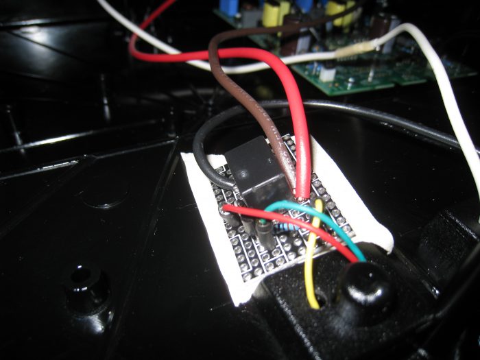
People often get their hearts broken on Valentine’s Day. Frying mine by playing with 120v AC is one way to do that. Kidding. Household AC is fine to tinker with as long as you’re careful. I built the circuit from the Arduino Relay guide to do the switching. I picked up a SPDT 5v power relay to make it easy to run off of the Arduino. The transistor is still necessary because the AVR can’t drive the 100+mA the relay needs to switch itself. I used an ATX power supply socket for convenience, rather than cutting a cable and using that. The neutral line from the socket is soldered to the neutral line on the sign. Each of the hot lines from the sign is connected to one of the relay throw positions, while the hot line from the socket is connected to the relay pole. Thus, toggling a pin high or low on the Arduino will flip the hot line from one half to the other, powering either the stop or go sign on. The project in total cost less than $20. It probably would have been under $15, but Radioshack is the only electronics store open on Sundays.

The code on the Arduino end is pretty simple. It just reads a character off the serial port and flips the relay one way or the other.

#define RELAY_PIN 13
bool state;
 
void setup()
{
  Serial.begin(9600);
  state = LOW;
  pinMode(RELAY_PIN, OUTPUT);
  digitalWrite(RELAY_PIN, state);
}
 
void loop()
{
  if (Serial.available()) {
    byte in = Serial.read();
    if (in == '0') {
      state = LOW;
      Serial.println("Switching relay to Stop.");
    } else if (in == '1') {
      state = HIGH;
      Serial.println("Switching relay to Go.");
    }
    digitalWrite(RELAY_PIN, state);
  }
}

The computer end can be whatever you want it to be. For example, in Python, you can use pySerial as follows.

>>> import serial
>>> sign = serial.Serial('/dev/ttyUSB0',9600)
>>> sign.write('0')
>>> sign.write('1')
1 Comment on Walk This Way: Pedestrian Traffic Light Status Indicator

Easy Absolute Orientation: PNI SpacePoint Fusion in Python

SpacePoint Fusion

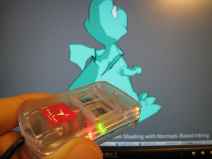
My college roommate Donnie mentioned the PNI SpacePoint Fusion in comments of the HMC5843 post, and it seemed too good to be true.  A 9 DOF controller (3 axes each of magnetometer, accelerometer, and gyro) with a Kalman filter to calculate a smooth quaternion that interfaces as a USB HID device, all for under $100.  I’d be surprised if PNI is making any profit on it.  I sound more like a shill than I’m normally comfortable with, but I’m truly impressed with this gadget. I have some plans for it involving a Microvision SHOWWX that I’m quite excited about; I’ll write more on that when it’s available in a couple of months.
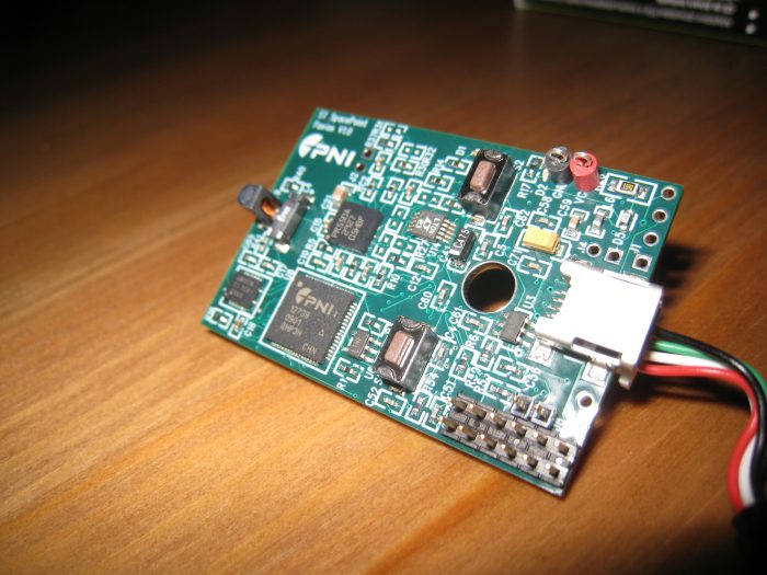
SpacePoint Fusion Innards

PNI provides some Windows only sample apps that show off how weirdly stable and precise the SpacePoint Fusion is.  Luckily, since it’s a normal USB HID device (redundant, I know), and PNI provides application notes, it’s easy to use on any platform.  I wrote a Python module that uses libhid via python-hid to make it easy to prototype with in Linux.  The usage is pretty simple, as shown below.  Note that when plugging the device in, you need to keep it still for a few seconds while the gyros are calibrated.  After that, the quaternion, accelerometer, and button data can be updated 62.5 times a second.

>>> import spacepoint
>>> fusion = spacepoint.SpacePoint()
>>> print repr(fusion.quat)
(0.987518310546875, -0.04425048828125, -0.04119873046875, 0.145294189453125)
>>> print repr(fusion.accel)
(-0.054016113354999999, 0.018859863306999999, -0.89648437622400001)
>>> print repr(fusion.buttons)
(0, 0)
>>> fusion.update()
>>> print repr(fusion)
accel: (-0.054016113354999999, 0.018859863306999999, -0.89648437622400001)
 quat: (0.97186279296875, -0.233428955078125, -0.030548095703125, 0.005401611328125)
 buttons: (0, 0)

Update on February 7, 2010: I emailed PNI about a bug in the firmware, and got the following response:

Thank you for submitting the SpacePoint bug regarding libusb, Python, and Linux. You’re right! There is a bug in the SpacePoint FW that prevented opening interface 1 without opening interface 0 when using libusb under Linux. While your work around was effective in allowing the device to operate normally, one should be able to open interface 1 directly without the work around. We were able to use your Python source code to quickly diagnose and repair the bug. Please see the attached for the modified Python script. Please feel free to post this paragraph, the modified code, and all bragging rights on your blog (https://eclecti.cc/).

Units being shipped now have the fix. I modified the Python module to handle units both with and without the firmware fix and bumped the version to 0.2.

Download:
SpacePoint Python Module
or
Standalone spacepoint.py

Setting udev rules to get the permissions right

In most cases, the module will just work properly.  However, if you get the following error, you probably don’t have the right permissions to access the usb device.

>>> import spacepoint
>>> fusion = spacepoint.SpacePoint()
hid_force_open failed with return code 12.

On most modern Linux distros, you can fix this by setting a udev rule for the device. In Ubuntu Karmic Koala, saving the following as /etc/udev/rules.d/45-spacepoint.rules , running sudo service udev restart , and then unplugging and replugging in the device should fix it:

# PNI SpacePoint Fusion
SYSFS{idVendor}=="20ff", SYSFS{idProduct}=="0100", MODE="0664", GROUP="admin"
11 Comments on Easy Absolute Orientation: PNI SpacePoint Fusion in Python

Sleep Remaining Indicator: A Laser Alarm Clock

Sleep remaining indicator

The chunk of title after the colon intends to serve as an explanation of what a sleep remaining indicator is. However, this project is neither an alarm nor a clock. It is a visual indicator of approximately how much time I have remaining to sleep in the night.

This may not be a problem you need solved. If, however, like me you wear glasses or contacts, the world when you are in bed turns into a blurry mess. Normally I reach over and unlock my phone or lean over and squint at my Chumby One, but those actions make it harder to get back to sleep. What I wanted was a way to instantly know how much longer I could sleep before my alarm would go off.

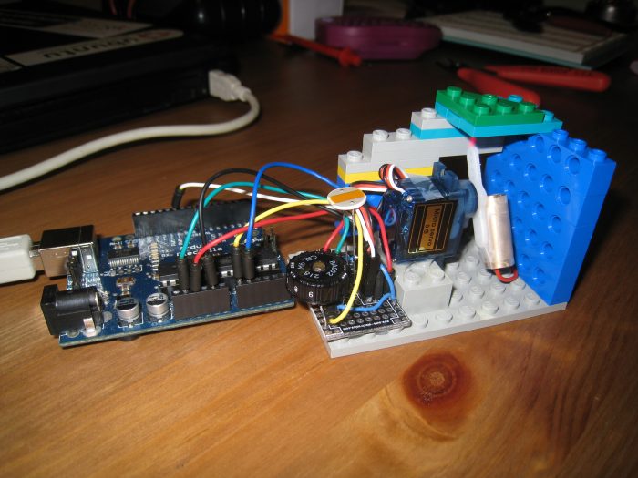
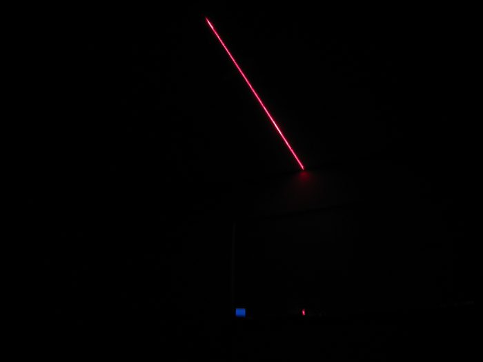
My solution involves a line laser, a servo, and an Arduino. I set a potentiometer with a number dial to approximately the right length of time in hours and hit the reset button. The servo with the line laser attached will shine the laser line onto the ceiling. The servo will then slowly rotate, moving the laser line underneath a cover made of Lego pieces, making the length of line showing on the ceiling shrink over the hours. It’s a little like an hourglass, but with lasers.

Laser line

Here’s the Arduino sketch. Use it under whatever license you want.

/* Sleep Remaining Indicator v1.0
 * by Nirav Patel <http://eclecti.cc>
 */
 
#include <Servo.h>
#include <math.h>
 
//#define photoPin 1
//#define laserPin 9
#define potPin 0
#define servoPin 10
#define M_PI_4 (M_PI/4.0)
#define MINSERVO 1190 // The laser line is no longer visible
#define MAXSERVO 1810 // The laser line is at its longest
 
unsigned long startTime;
unsigned long totalTime;
unsigned int lastVal;
Servo laserServo;
 
void setup()
{
  Serial.begin(9600);
//  pinMode(photoPin, INPUT);
  pinMode(potPin, INPUT);
 
  // this magic converts the pot value to 0 to 9 hours in milliseconds.
  totalTime = (unsigned long)31641*(unsigned long)(1024-analogRead(potPin));
  Serial.print('Time in hours: ');
  Serial.println((double)totalTime/(double)3600000.0);
 
  laserServo.attach(servoPin);
  startTime = millis();
  lastVal = 0;
}
 
void loop()
{
  // The laser brightness should depend on the ambient light in the room.
  // Unfortunately, my laser dislikes PWM, so I just have it hooked to 3.3v
//  unsigned int light = analogRead(photoPin);
//  analogWrite(laserPin,light>>2);
 
  // calculate the time we've been running (well, sleeping)
  unsigned long time = millis()-startTime;
  // Note that one could use this as an alarm clock by setting off a buzzer or
  // even having the servo rotate loudly
  if (time > totalTime) {
    laserServo.writeMicroseconds(MINSERVO);
    while(1) {}
  }
 
  // This trig makes the line length shrink uniformly over time.
  time = totalTime-time;
  double angle = atan2((double)time,(double)totalTime);
  unsigned int servoVal =  (unsigned int)((angle/M_PI_4)*(double)(MAXSERVO-MINSERVO))+MINSERVO;
 
  servoVal = (servoVal > MAXSERVO? MAXSERVO : (servoVal < MINSERVO ? MINSERVO : servoVal));
  // The servo is imperfect, so don't move unless the value actually changed
  if (servoVal != lastVal) {
    Serial.println(servoVal);
    laserServo.writeMicroseconds(servoVal);
    lastVal = servoVal;
  }
 
  // tick like a clock
  delay(1000);
}
10 Comments on Sleep Remaining Indicator: A Laser Alarm Clock

Urban Moonshining: Home Distilling for Fun and (not) Profit

Copper Pot Still
At some point in high school, my friends and I decided to learn the lost craft of home distillation. We started with the best of intentions (well, not really), but were unable to build stills that functioned until we hit college. Since then, we have just about perfected the process of distilling tasty, cheap rum on a stove top. John Martin has chronicled our steps and missteps over the years in a series of blog posts. The first three cover the background story, the basics of fermenting a rum wash, and the general process of distillation. The final post covers the specifics of urban moonshining; that is, plans for a micro still that allows for home distilling within the confines of the average apartment.

Stove Top Still

4 Comments on Urban Moonshining: Home Distilling for Fun and (not) Profit

HMC5843 Magnetometer Library for Arduino

HMC5843 and Arduino

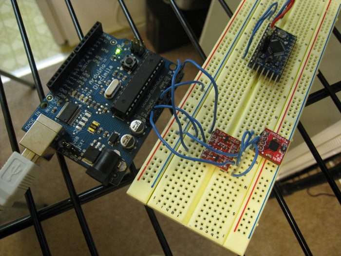
I (finally) have a project taking up the idle cycles of my brain, the first step of which involves figuring out how to use a magnetometer.  The project will eventually use the digital compass, accelerometers, perhaps a gyro, and maybe absolute forms of positioning like an IR camera.  I’m being slightly vague about this project both because the idea is by far the coolest thing I’ve ever come up with and because it is still somewhat short of half baked.

Anyway, Honeywell recently released a rather reasonably priced three axis magnetometer, the HMC5843, which SparkFun carries a breakout board for.  It interfaces over i2c, which is conveniently supported in hardware by most AVR microcontrollers, including the ones used on Arduino.  Arduino is something of paradox.  On one hard, the hardware is so simple and easy to use, vastly cutting down on the amount of time I need to spend arranging parts on a breadboard.  On the other hand, computations that should take a few operations instead call long functions that get compiled into hundreds, and the IDE makes me want to stab a stick of RAM into my jugular.  Luckily, one can mitigate the downsides by using an external editor, communicating with cutecom/minicom, and using avr-libc instead of the Arduino libraries as much as possible.  Back to the project.

The actual circuit is fairly simple.  Analog pins 4 and 5 on the Arduino serve as i2c’s SDA and SDC lines, respectively.  I’m using a level shifter from SparkFun to get the Arduino’s 5v lines down to the 3.3v that the HMC5843 is looking for.  Note that one can skip this by using a 3.3v Arduino Pro.  The FTDI chip on the Arduino outputs 3.3v, which is brought out on the headers, allowing the level shifter and the magnetometer to be powered off the Arduino.

I tried using the Arduino Wire library for i2c communication, but had no luck.  Atmel made TWI, the i2c implementation on the AVR, fairly easy to use, so I read through the datasheet, looked at some examples, and wrote my own Arduino library specifically for the HMC5843.  The current implementation is absolutely alpha, but it seems to read the x, y, and z values at 10 Hz correctly.  Note that you probably can’t use this library at the same time as Wire or another i2c library, and that it also doesn’t support having multiple i2c devices connected.  Its sole purpose is interfacing the HMC5843.  Here is an example sketch using it:

#include <HMC.h>
 
void setup()
{
  Serial.begin(9600);
  delay(5); // The HMC5843 needs 5ms before it will communicate
  HMC.init();
}
 
void loop()
{
  int x,y,z;
  delay(100); // There will be new values every 100ms
  HMC.getValues(&x,&y,&z);
  Serial.print("x:");
  Serial.print(x);
  Serial.print(" y:");
  Serial.print(y);
  Serial.print(" z:");
  Serial.println(z);
}

Continuing the theme of a different license for each set of code I release, this library is under a two clause BSD style license.  Please feel free to try it out and give me feedback/suggestions/patches/pedantic advice/flames.

Download and extract into the hardware/libraries/ folder of your Arduino directory:
HMC.zip

44 Comments on HMC5843 Magnetometer Library for Arduino