Parametric M.2 Mockup Generator

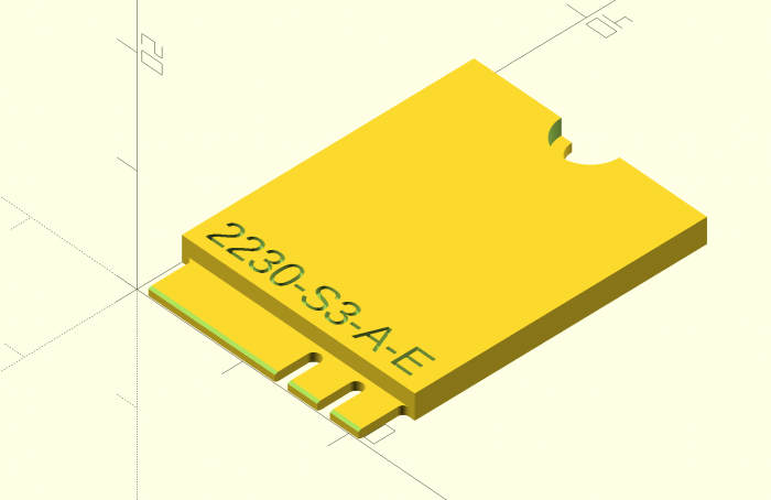
The thing I’m sharing today is a very early and very small slice of the project that is likely going to consume the next few years of my life. This is a parametric generator for M.2 expansion card mockups in OpenSCAD.

I can’t imagine this is useful to many people, but the beauty of open source software and hardware is that it doesn’t have to be. Even if only one person happens upon this years down the road and it saves them a few hours or gives them the reference point they needed, it was worth sharing. Sharing knowledge isn’t zero-sum; it’s exponential (though maybe not in this specific instance).

// M.2 Mockup Generator
// by Nirav Patel <https://eclecti.cc>
//
// To the extent possible under law, Nirav Patel has waived all copyright
// and related or neighboring rights to M.2 Mockup Generator.
//
// An easy to use parametric M.2 mockup generator.
// See https://en.wikipedia.org/wiki/M.2 for more information about the 
// M.2 (formerly NGFF) standard.

edge_width = 19.85;
edge_length = 4;
edge_r = 0.5;
hole_r = 1.75;
key_r = 0.6;
key_length = 3.5;

pcb_thick = 0.8;
bottom_edge_keepout = 5.2;
top_gnd_pad_r = 2.75;
bottom_gnd_pad_r = 3;
bottom_gnd_pad_offset = 1;
bevel = 0.3;
bevel_angle = 20;

$fn=50;

module key_cutout() {
    union() {
        translate([0, key_length - key_r]) circle(r = key_r);
        translate([-key_r, -1]) square([key_r*2,key_length - key_r +1]);
    }
}

function get_key(key_type="mm") =
    key_table[search([key_type],key_table,1,0)[0]][1];

key_table = [["", 100], ["A", 6.625], ["B", 5.625], ["C", 4.625], ["D", 3.625], ["E", 2.625], ["F", 1.625], ["G", -1.125], ["H", -2.125], ["J", -3.125], ["K", -4.125], ["L", -5.125], ["M", -6.125]];

module m2_2d(width=22, length=30, key="M", key2="") {
    // Start with a 2d version
    difference() {
        square([width, length]);
        
        // Left cutout
        translate([(width-edge_width)/2-width, -edge_r]) square([width, edge_length]);
        translate([(width-edge_width)/2-width-edge_r, 0]) square([width, edge_length]);
        translate([(width-edge_width)/2-edge_r, edge_length-edge_r]) circle(r=edge_r);
        
        // Right cutout
        translate([width-(width-edge_width)/2, -edge_r]) square([width, edge_length]);
        translate([width-(width-edge_width)/2+edge_r, 0]) square([width, edge_length]);
        translate([width-(width-edge_width)/2+edge_r, edge_length-edge_r]) circle(r=edge_r);
        
        // Hole cutout
        translate([width/2, length]) circle(r = hole_r);
        
        // Key cutouts
        translate([width/2 + get_key(key), 0])
            key_cutout();
        
        translate([width/2 + get_key(key2), 0])
            key_cutout();
    }
}

module m2_text(width=22, length=30, height="", key="", key2="") {
    if (key2 != "") {
        string = str(width, length, "-", height, "-", key, "-", key2);
        linear_extrude(height = 1)
            text(string, size = 2.5);
    } else {
        string = str(width, length, "-", height, "-", key);
        linear_extrude(height = 1)
            text(string, size = 2.5);
    }
}

module m2(width=22, length=30, height="", key="", key2="") {
    union() {
        difference() {
            linear_extrude(height = pcb_thick)
                m2_2d(width, length, key, key2);
            
            // The card edge bevel
            translate([0, bevel, 0]) rotate([180-bevel_angle, 0, 0]) cube([width, 10, 10]);
            translate([0, bevel, pcb_thick]) rotate([90+bevel_angle, 0, 0]) cube([width, 10, 10]);
        }
        
        difference() {
            // The various component keepout zones and embossed text
            if (height == "S1") {
                difference() {
                    translate([0, edge_length, pcb_thick]) cube([width, length-edge_length, 1.2]);
                    translate([1, edge_length+1, pcb_thick+1.2-0.5]) m2_text(width, length, height, key, key2);
                }
            } else if (height == "S2") {
                difference() {
                    translate([0, edge_length, pcb_thick]) cube([width, length-edge_length, 1.35]);
                    translate([1, edge_length+1, pcb_thick+1.35-0.5]) m2_text(width, length, height, key, key2);
                }
            } else if (height == "S3") {
                difference() {
                    translate([0, edge_length, pcb_thick]) cube([width, length-edge_length, 1.5]);
                    translate([1, edge_length+1, pcb_thick+1.5-0.5]) m2_text(width, length, height, key, key2);
                }
            } else if (height == "D1") {
                difference() {
                    translate([0, edge_length, pcb_thick]) cube([width, length-edge_length, 1.2]);
                    translate([1, edge_length+1, pcb_thick+1.2-0.5]) m2_text(width, length, height, key, key2);
                }
                translate([0, bottom_edge_keepout, -1.35]) cube([width, length-bottom_edge_keepout, 1.35]);
            } else if (height == "D2") {
                difference() {
                    translate([0, edge_length, pcb_thick]) cube([width, length-edge_length, 1.35]);
                    translate([1, edge_length+1, pcb_thick+1.35-0.5]) m2_text(width, length, height, key, key2);
                }
                translate([0, bottom_edge_keepout, -1.35]) cube([width, length-bottom_edge_keepout, 1.35]);
            } else if (height == "D3") {
                difference() {
                    translate([0, edge_length, pcb_thick]) cube([width, length-edge_length, 1.5]);
                    translate([1, edge_length+1, pcb_thick+1.5-0.5]) m2_text(width, length, height, key, key2);
                }
                translate([0, bottom_edge_keepout, -1.35]) cube([width, length-bottom_edge_keepout, 1.35]);
            } else if (height == "D4") {
                difference() {
                    translate([0, edge_length, pcb_thick]) cube([width, length-edge_length, 1.5]);
                    translate([1, edge_length+1, pcb_thick+1.5-0.5]) m2_text(width, length, height, key, key2);
                }
                translate([0, bottom_edge_keepout, -0.7]) cube([width, length-bottom_edge_keepout, 0.7]);
            } else if (height == "D5") {
                difference() {
                    translate([0, edge_length, pcb_thick]) cube([width, length-edge_length, 1.5]);
                    translate([1, edge_length+1, pcb_thick+1.5-0.5]) m2_text(width, length, height, key, key2);
                }
                translate([0, bottom_edge_keepout, -1.5]) cube([width, length-bottom_edge_keepout, 1.5]);
            } else {
                translate([1, edge_length+1, pcb_thick-0.5]) m2_text(width, length, height, key, key2);
            }
            
            // The ground pad keepouts
            translate([width/2, length, pcb_thick]) cylinder(r = top_gnd_pad_r, h = 10);
            translate([width/2, length-bottom_gnd_pad_offset, -10]) {
                cylinder(r = bottom_gnd_pad_r, h = 10);
                translate([-bottom_gnd_pad_r, 0, 0]) cube([bottom_gnd_pad_r*2, bottom_gnd_pad_offset, 10]);
            }
        }
    }
}

m2(width=22, length=30, height="S3", key="A", key2="E");

This is also up on GitHub as a Gist.

1 Comment on Parametric M.2 Mockup Generator

Fully Parametric 3D Printable Computer Case

Modeled in OpenSCAD
When looking into small form factor cases to build a Mini-ITX PC for my Rift, I found a few things:

  1. Like any other hobby, there is an obsessive (in a good way) community of small form factor enthusiasts.
  2. The metric they optimize for is case size in liters.
  3. Often, people are stuck sub-optimally limiting their component selection to the case they want or their case selection to fit the components they have.

Rather than limiting choice or ending up with a larger than desired case, why not make your case exactly match the size of the components you want with no wasted space?  It turns out that a Mini-ITX motherboard, SFX power supply, and short GPU just barely fit within the bounds of a Prusa i3 MK3 3D printer, so I decided to solve exactly that with an open source fully parametric printable case in OpenSCAD.  That means you can input the components you have or edit a few dimensions and output a bespoke case that fits them perfectly.  To win community brownie points, the volume of the case is also automatically generated and embossed on the side.

Just barely fits.
Partly for rigidity and partly for simplicity of design and assembly, I decided to make it effectively a bucket with most of the case being a single print. I started with a traditional “shoebox” layout to keep it simple as well. The only other parts are the lid and optional feet (printable in flexible material like TPU). I also used threaded inserts rather than screwing into plastic to allow re-assembly without destroying the case.

I referenced the Mini-ITX and PCI-e specs to get the proper dimensions, and measured the components I had on hand and pulled some datasheets online for specifics on heatsinks and the GPU. There is pretty good ventilation all around, with the default configuration that fits my components having a 140mm intake fan and a mostly isolated GPU with dedicated intake and exhaust.

Un-intentionally two-tone.
It took me three or four iterations of prints (~36 hours and ~400g/$8 of plastic each) to get to a level of completeness that I’m happy with using and publishing, but there is certainly more to improve.  Since it is open source, revisions and fixes are welcome.

I tried to make it as simple as possible to customize by having keyword fields for the power supply type and heatsink chosen. The PSU can be SFX, SFX-L, or FlexATX, and heatsink can be a 120mm AIO, Noctua NH-L12s, Noctua NH-U9s, or Cryorig C7. If you have any of those and the same GPU I have (Zotac 1080 Mini), you can just edit the keywords and the case will be automatically generated to fit them. If you want to make deeper changes or use different components, you can do so by editing the .scad files.

traditional(show_body = true, show_lid = false, show_internals = false, heatsink_type = "noctua_nh_l12s", psu_type = "sfx");

The two-tone is unintentional. I ran out of filament partway through.
The full CAD, example ready-to-print .stl files, and instructions are up on GitHub, licensed under an Open Source 2-Clause BSD license.  You can also follow along the development thread at SFF Forum.

7 Comments on Fully Parametric 3D Printable Computer Case

Revisiting RepRap 8 years later with a Prusa i3 MK3

You can see the resemblance.
It’s remarkable how much and how little has changed with RepRap since I built a Mendel in late 2010.  The basic architecture has proven incredibly robust.  The most popular home 3D printers including the Prusa i3 MK3 that I bought still use an open frame with a moving bed on a belt for Y, moving extruder on a belt for X, dual driven lead screws for Z, gear driven filament into a hot end with a heat break and heat block, a 0.4mm nozzle, and an ATmega2560 for control.  I suspect if I dug into the firmware, I’d even find some source in common between the Prusa firmware on the MK3 and Sprinter firmware I used on the Mendel.

The seal of excellence.
That may sound like criticism, but I actually mean it as praise.  Over the last 8 years, there have been hundreds of diverging and converging iterations on the Mendel formula enabled by its open source nature, with each fixing flaws and adding improvements over the last.  It took me about two months of research to get the right parts and another two months of building and tuning to get my old Mendel to print anything at all, and it took a stack of hacks and modifications of mechanical design, circuitry, firmware, and host software that meant I was probably the only person who could speak the incantations required to operate the thing.  With the MK3, it took 4-5 hours of assembly (by choice; you can order it pre-assembled) and absolutely no configuration to get to a perfect first print, and there are thousands of people with the same configuration.

It's hard to take a picture of a light.
The printer isn’t perfect, but again open source comes to the rescue.  I had taken a few months hiatus using a Monoprice Mini Delta 3D Printer, and while it was a nice tool, it had a range of bugs and irritating flaws that were challenging or impossible to correct.  With the Prusa, I found that I needed a light to provide illumination for the webcam attached to the OctoPrint Raspberry Pi driving it.  I was able to pull up the schematic and rig up an LED strip trivially.  I’ve posted up the CAD and instructions on Thingiverse so anyone else with an MK3 or derived printer can do it too!

1 Comment on Revisiting RepRap 8 years later with a Prusa i3 MK3

Tiny USB Type C Adjustable Power Supply

Tiny Power Supply
When building projects professionally, I try to take every shortcut possible to accelerate learnings around an idea and get useful results to inform the next iteration. When building projects personally, I do basically the opposite. Often when starting with an idea, I’ll find that it would be helpful to build a tool to execute on the idea cleanly, so I switch tracks to building the tool. Sometimes, when trying to build that tool, I’ll find that I’m missing some other tool and build that instead. This is one of those.

The guts
I couldn’t find an adjustable power supply in my house (I think my personal one became property of Oculus at some point), and I couldn’t find a small simple one that I liked online, so I built the one I wanted. This is just a 3d printed housing with a PD Buddy USB Type C board, a Rui Deng DPS5005 Switching Power Supply, and banana plug terminals inside. It supports around 0-19V output from a 20V Type C power supply like a MacBook Pro charger and up to 5A. Rui Deng’s DPS3005 would technically also be sufficient if you want to save a few bucks. The result is a cute little adjustable desktop power supply that solves for what most of my projects need. The OpenSCAD and STL files along with assembly instructions are on Thingiverse.

Not the world's most accurate power supply.

1 Comment on Tiny USB Type C Adjustable Power Supply

Blinded by the Light: DIY Retinal Projection

Retinal Projection

After grabbing a couple of Microvision SHOWWX laser picoprojectors when they went up on Woot a few months back, I started looking for ways to use them.  Microvision started out of a project at the University of Washington HITLab in 1994 to develop laser based virtual retinal displays.  That is, a display that projects an image directly onto the user’s retina.  This allows for a potentially very compact see through display that is only visible by the user.  The system they developed reflected lasers off of a mechanical resonant scanner to deflect them vertically and horizontally, placing pixels at the right locations to form an image.  The lasers were modulated to vary the brightness of the pixels.  The SHOWWX is essentially this setup after 15 years of development to make it inexpensive and miniaturize it to pocket size.  The rest of the retinal display system was a set of optics designed to reduce the scanned image down to a point at the user’s pupil.  I thought I would try to shrink and cheapen that part of it as well.

The setup I built is basically what Michael Tidwell describes in his Virtual Retinal Displays thesis.  The projected image passes through a beamsplitter where some of the light is reflected away, reflects off of a spherical concave mirror to reduce back down to a point, and hits the other side of the beamsplitter, where some of the light passes through and the rest is reflected to the user’s pupil along with light passing through the splitter from the outside world.  For the sake of cost savings, all of my mirrors are from the bargain bin of Anchor Optics.  The key to the project is picking the right size and focal length of the spherical mirror.  The larger setup in the picture below uses a 57mm focal length mirror, which results in a fairly large rig with the laser scanner sitting at twice the focal length (the center of curvature) away from the mirror.  The smaller setup has a focal length around 27mm, which results in an image that is too close to focus on unless I take my contact lenses out.  The mirror also has to be large enough to cover most of the projected image, which means the radius should be at least ~0.4x the focal length for the 24.3° height and at most ~0.8x for the 43.2° width coming from a SHOWWX.  Note that this also puts the field of view of the virtual image entering the eye somewhere between a 24.3° diameter circle and a 24.3° by 43.2° rounded rectangle.

Projection Rig

Aside from my inability to find properly shaped mirrors, the big weakness of this rig is the size of the exit pupil.  The exit pupil is basically the useful size of the image leaving the system.  In this case, it is the width of the point that hits the user’s pupil.  If the point is too small, eye movement will cause eye pupil to miss the image entirely.  Because the projector is at the center of curvature of the mirror (see the optical invariant), the exit pupil is the same the width as the laser beams coming out of the projector: around 1.5 mm wide.  This makes it completely impractical to use head mounted or really, any other way.  I paused work on this project a few months ago with the intention of coming back to it when I could think of a way around this.  With usable see through consumer head mounted displays just around the bend though, I figured it was time to abandon the project and publish the mistakes I’ve made in case it helps anyone else.

If you do want to build something like this, keep in mind that the title of this post is only half joking.  I don’t normally use bold, but this is extra important: If you don’t significantly reduce the intensity of light coming from the projector, you will damage your eyes, possibly permanently.  The HITLab system had a maximum laser power output of around 2 μW.  The SHOWWX has a maximum of 200mW, which is 100,000x as much!  Some folks at the HITLab published a paper on retinal display safety and determined that the maximum permissible exposure from a long term laser display source is around 150 μW, so I needed to reduce the power by at least 10,000x to have a reasonable safety margin.  As you can see in the picture above, I glued a ND1024 neutral density filter over the exit of the projector, which reduces the output to 0.1%.  Additionally, the beamsplitter I picked reflects away 10% of the light after it exits the projector, and 90% of what bounces off of the concave mirror.  Between the ND filter, the beamsplitter, and setting the projector to its lowest brightness setting, the system should be safe to use.  The STL file and a fairly ugly parametric OpenSCAD file for the 3D printed rig to hold it all together are below.

blinded.scad
blinded.stl

17 Comments on Blinded by the Light: DIY Retinal Projection

Semi-Automatic Paintbrush

The Mona Lisa

I bought an InkShield from the Kickstarter a few months ago mostly out of a desire to support an interesting Open Hardware project.  It wasn’t until yesterday that I thought of something useful to do with it.  Instead of that, I made this project, called the Semi-Automatic Paintbrush.  Using an infrared camera, an InkShield, an ink cartridge with an infrared LED stuck to it, and your arm, you can copy great works of art, or just any old picture.

The desktop side software involved is called paintbrush.py.  It conveniently uses the homography module I wrote a year ago to map what the IR camera sees to the coordinate system of the canvas.  The mapping is calibrated interactively by placing the cartridge/LED at each of the four corners of the canvas and pressing a key when prompted.  After that, the motion of the LED is tracked, the corresponding region of the image is found, and the script sends serial commands to an Arduino with the InkShield telling it which nozzles to fire at what duty cycle to achieve the correct level of gray, or in this case, green.  The painted regions are tracked to prevent flooding.

As you can see from the image above, the results are not going to end up in the Louvre, but they do have a kind of partially mechanical, partially organic flavor to them.  If you have an InkShield, an IR LED, and a pygame supported IR camera (I use a modified PS3 Eye), and you’re interested in making your own lazy artwork, the script is available on github under an ISC License.  The Arduino sketch requires the InkShield library and is LGPL.  Usage instructions for the script are contained with it.

5 Comments on Semi-Automatic Paintbrush

For Sale: RepRap Parts for Bitcoins

SAE Prusa Mendel RepRap Parts

Bitcoin is exactly the kind of fantastic real life science fiction kind of project that I enjoy: a peer to peer, anonymous, cryptographically secure currency.  I’m not even an armchair economist, but I suspect the hardest part of starting any new economy is the chicken and the egg problem.  Sellers won’t join the market unless there are potential buyers, and buyers won’t join unless there are people selling things they want to buy.  Unfortunately in the case of Bitcoin, both the chicken and the egg have been eaten by the monster called currency speculation.  It is likely that the majority of actual transactions are between speculators and exchanges, taking advantage of volatility to make a profit in BTC or USD.  Half a paragraph later, I’m still not an economist, but I also suspect that as a larger fraction of the economy goes to goods and services, the currency will stabilize, encouraging more people to use it.  Therefore, I am doing my part in bootstrapping the Bitcoin economy by using a project that loves to bootstrap.

Wade's Extruder and spare parts

I’m selling a set of SAE Prusa Mendel parts printed on the Mendel used in many of my recent projects.  The parts are from the current files in the PrusaMendel git repository, and are printed in PLA.  They are quite clean and strong, but may need a little work with a knife or drill bit.  The Wade’s Extruder and PLA bushings from the repository are also included.  But wait, there’s more!  Between getting misaligned on the trip home from Maker Faire and a torn belt, my printer was in fairly rough shape for a few weeks.  While repairing it, I printed RepRap parts to test the calibration.  I’m including the usable parts printed during that time and some more good spare parts I printed recently; this is the pile on the left in the bottom picture.  The full set of good parts from the top picture and the Wade’s Extruder are in separate bags.

I’m selling this set for the hopefully reasonable price of 5 BTC, shipped USPS Priority Mail to anywhere in the US.  At the exchange rate at this moment, that is roughly $72.50.  It could be $20 or $200 by tomorrow for all I know, but I’m willing to take the risk if you are.  Email me, and we can arrange the transaction. Sold!  There was less interest than I was hoping for, so I probably won’t be doing it again.

4 Comments on For Sale: RepRap Parts for Bitcoins

Physical Keygen: Now for Disc Detainer Locks

ABUS Plus Disc Lock

The Physical Keygen post got reactions, but there was a common claim among many of them that it was just a gimmick because there are more practical ways of getting past basic Schlage and Kwikset pin tumbler locks.  I agree with that, and I’ll also admit that a fair number of my projects are gimmicks, or as a stretch, art.  Schuyler Towne of Open Locksport saw past the gimmick (or art) and into the possibility of printing keys for more interesting locks.

He stopped by recently with a collection of said locks, and over the period of a few hours we determined that keys for disc detainer locks were printable and created a nearly working ABUS Plus key.  He left me a cutaway lock, and over the next week, I refined the model to the point of working straight off of the printer.  Despite being a higher security lock than the SC1 or KW1 pin tumblers I was working with before, the key is much easier to print accurately.  The OpenSCAD model is linked below, and like the last files, you simply edit the last line to match the code for your key.

The ABUS Plus and other disc detainer locks are much more common in Europe than the US, but we do have a pretty ubiquitous example around here.  After the Bic Pen debacle in 2004, Kryptonite switched their bicycle U-locks from tubular to disc detainer.  I designed a model off of the key from the Kryptonite Evolution I have, but as of yet, I have not successfully opened the lock with it.  The key is smaller and thinner than the ABUS Plus, causing it to flex too much to effectively turn the last few discs.  I’ve posted the file anyway, in case someone has stronger plastic or an idea to strengthen the model.

Edit: The Kryptonite key works. I tightened my X and Y belts and printed it a bit slower. Apparently some of the blobbing on the corners before was catching on disks.

Download:
abus_plus.scad
kryptonite.scad

2 Comments on Physical Keygen: Now for Disc Detainer Locks