This is why you haven’t heard from me in months
Blinded by the Light: DIY Retinal Projection
After grabbing a couple of Microvision SHOWWX laser picoprojectors when they went up on Woot a few months back, I started looking for ways to use them. Microvision started out of a project at the University of Washington HITLab in 1994 to develop laser based virtual retinal displays. That is, a display that projects an image directly onto the user’s retina. This allows for a potentially very compact see through display that is only visible by the user. The system they developed reflected lasers off of a mechanical resonant scanner to deflect them vertically and horizontally, placing pixels at the right locations to form an image. The lasers were modulated to vary the brightness of the pixels. The SHOWWX is essentially this setup after 15 years of development to make it inexpensive and miniaturize it to pocket size. The rest of the retinal display system was a set of optics designed to reduce the scanned image down to a point at the user’s pupil. I thought I would try to shrink and cheapen that part of it as well.
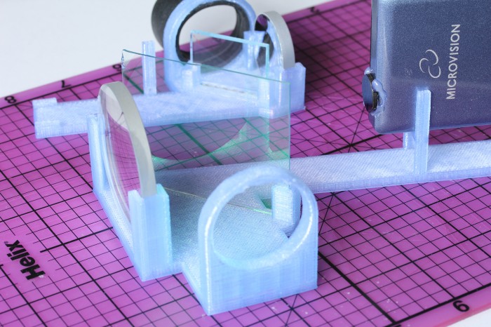
The setup I built is basically what Michael Tidwell describes in his Virtual Retinal Displays thesis. The projected image passes through a beamsplitter where some of the light is reflected away, reflects off of a spherical concave mirror to reduce back down to a point, and hits the other side of the beamsplitter, where some of the light passes through and the rest is reflected to the user’s pupil along with light passing through the splitter from the outside world. For the sake of cost savings, all of my mirrors are from the bargain bin of Anchor Optics. The key to the project is picking the right size and focal length of the spherical mirror. The larger setup in the picture below uses a 57mm focal length mirror, which results in a fairly large rig with the laser scanner sitting at twice the focal length (the center of curvature) away from the mirror. The smaller setup has a focal length around 27mm, which results in an image that is too close to focus on unless I take my contact lenses out. The mirror also has to be large enough to cover most of the projected image, which means the radius should be at least ~0.4x the focal length for the 24.3° height and at most ~0.8x for the 43.2° width coming from a SHOWWX. Note that this also puts the field of view of the virtual image entering the eye somewhere between a 24.3° diameter circle and a 24.3° by 43.2° rounded rectangle.
Aside from my inability to find properly shaped mirrors, the big weakness of this rig is the size of the exit pupil. The exit pupil is basically the useful size of the image leaving the system. In this case, it is the width of the point that hits the user’s pupil. If the point is too small, eye movement will cause eye pupil to miss the image entirely. Because the projector is at the center of curvature of the mirror (see the optical invariant), the exit pupil is the same the width as the laser beams coming out of the projector: around 1.5 mm wide. This makes it completely impractical to use head mounted or really, any other way. I paused work on this project a few months ago with the intention of coming back to it when I could think of a way around this. With usable see through consumer head mounted displays just around the bend though, I figured it was time to abandon the project and publish the mistakes I’ve made in case it helps anyone else.
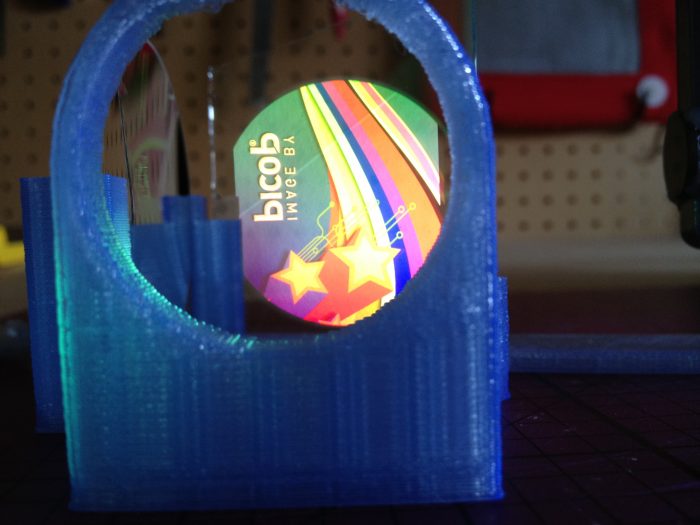
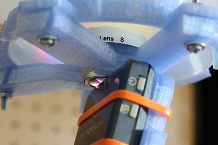
If you do want to build something like this, keep in mind that the title of this post is only half joking. I don’t normally use bold, but this is extra important: If you don’t significantly reduce the intensity of light coming from the projector, you will damage your eyes, possibly permanently. The HITLab system had a maximum laser power output of around 2 μW. The SHOWWX has a maximum of 200mW, which is 100,000x as much! Some folks at the HITLab published a paper on retinal display safety and determined that the maximum permissible exposure from a long term laser display source is around 150 μW, so I needed to reduce the power by at least 10,000x to have a reasonable safety margin. As you can see in the picture above, I glued a ND1024 neutral density filter over the exit of the projector, which reduces the output to 0.1%. Additionally, the beamsplitter I picked reflects away 10% of the light after it exits the projector, and 90% of what bounces off of the concave mirror. Between the ND filter, the beamsplitter, and setting the projector to its lowest brightness setting, the system should be safe to use. The STL file and a fairly ugly parametric OpenSCAD file for the 3D printed rig to hold it all together are below.
Snow Globe: Part One, Cheap DIY Spherical Projection
Since reading Snow Crash, I’ve been drawn to the idea of having my own personal Earth. Because I’m stuck in reality and the virtual version of it is always 5 years away, I’m building a physical artifact that approximates the idea: an interactive spherical display. This is of course something that exists and can likely be found at your local science center. The ones they use are typically 30-100″ in diameter and cost enough that they don’t have prices publicly listed. Snow Globe is my 8″ diameter version that costs around $200 to build if you didn’t buy a Microvision SHOWWX for $600 when they launched like I did.
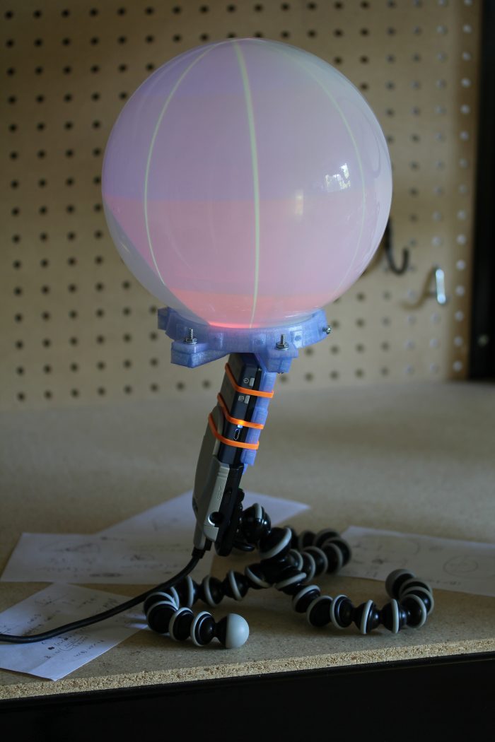
The basic design here is to shoot a picoprojector through a 180° fisheye lens into a frosted glass globe. The projector is a SHOWWX since I already have one, but it likely works better than any of the non-laser alternatives since you avoid having to deal with keeping the surface of the sphere focused. Microvision also publishes some useful specs, and if you ask nicely, they’ll email you a .STL model of their projector. The lens is an Opteka fisheye designed to be attached to handheld camcorders. It is by far the cheapest 180° lens I could find with a large enough opening to project through. The globe, as in my last dome based project is for use on lighting fixtures. This time I bought one from the local hardware store for $6 instead of taking the one in my bathroom.
I’ve had a lot of fun recently copying keys and people, but my objective in building a 3D printer was to make it easier to do projects like this one. Designing a model in OpenSCAD, printing it, tweaking it, and repeating as necessary is much simpler than any other fabrication technique I’m capable of. In this case, I printed a mount that attaches the lens to the correct spot in front of the projector at a 12.15° angle to center the projected image. I also printed brackets to attach the globe to the lens/projector mount. The whole thing is sitting on a GorillaPod until I get around to building something more permanent.
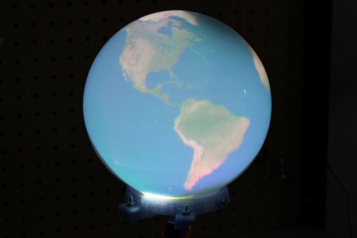
Actually calibrating a projector with slight pincushion through a $25 lens into a bathroom fixture attached together with some guesswork and a 3D printer is well beyond my linear algebra skill, so I simplified the calibration procedure down to four terms. We need to find the radius in pixels of the circle being projected and the x and y position of the center of that circle for starters. The more difficult part, which tested my extremely rusty memory of trigonometry is figuring out how to map the hemisphere coming out of the fisheye lens to the spherical display surface. For that, we have a single number for the distance from the center of the sphere to the lens, in terms of a ratio of the projected radius. The math is all available in the code, but the calibration script I wrote is pretty simple to use. It uses pygame to project longitude lines and latitude color sections as in the image above. You use the arrow keys to line up the longitude lines correctly to arrive at the x and y position, plus and minus keys to adjust the radius size until it fits the full visible area of the sphere, and 9 and 0 to adjust the lens offset until the latitudes look properly aligned. What you end up with is close enough to correct to look good, though as you can see in the images, the projector doesn’t quite fit the lens or fill the sphere. The script saves the calibration information in a pickle file for use elsewhere.
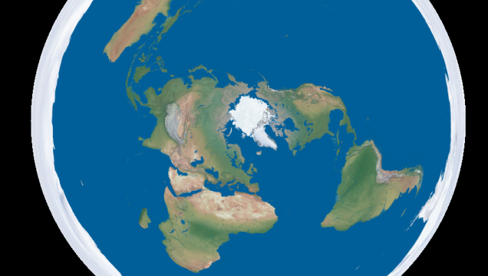
Going back to the initial goal, I wrote a script to turn equirectangular projected maps of the Earth into roughly azimuthal equidistant projected images calibrated for a Snow Globe like the one above. There are plenty of maps of the former projection available freely, like Natural Earth and Blue Marble. Written in python, the script is quite slow, but it serves as a proof of concept. The script, along with the calibration script and the models for the 3D printed mounts are all available on github. I’ve finally fully accepted git and no longer see a point in attaching the files to these posts themselves. I put a Part One in the title to warn you that this blog is going to be all Snow Globe all the time for the foreseeable future. Up next is writing a faster interface to interactively display to it in real time, and if I think of a good way to do it, touch input is coming after that.
Download from github:
git://github.com/nrpatel/SnowGlobe.git
Projecting Virtual Reality with a Microvision SHOWWX
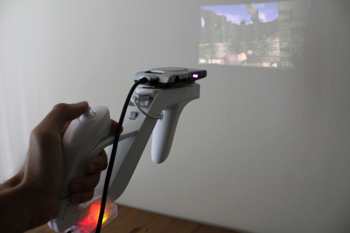
It’s bit of a stretch to call this Virtual Reality, in capitals no less, but I can’t think of another noun that fits it better. This is the idea I have been hinting about, sprouted into a proof of concept. By combining the stable positioning of the SpacePoint Fusion with the always in focus Microvision SHOWWX picoprojector, one can create a pretty convincing glasses-free virtual reality setup in any smallish dark room, like the bedroom in my Bay Area apartment.
This setup uses the SpacePoint to control the yaw, pitch, and roll of the camera, letting you look and aim around the virtual environment that is projected around you. A Wii Remote and Nunchuk provide a joystick for movement and buttons for firing, jumping, and switching weapons. All of the items are mounted to a Wii Zapper. For now, it is annoyingly all wired to a laptop I carried around in a backpack. Eventually, I’m planning on using a BeagleBoard and making the whole projector/computer/controller/gun setup self-contained.
The software is a hacked version of Cube, a lightweight open source first person shooter. It’s no Crysis 2, but it runs well on Mesa on integrated graphics, and it’s a lot easier to modify for this purpose than Quake 3. Input is via libhid for the SpacePoint and CWiid for the Wiimote. All in all, it actually works pretty well. The narrow field of view and immersiveness (a word, despite what my dictionary claims) makes playing an FPS quite a bit scarier for those who are easily spooked, like yours truly. There is some serious potential in the horror/zombie/velociraptor genres for a device like this, if anyone is interested in designing a game.
This is just the start, of course. I know I say that a lot, and there are about a dozen projects on this blog I’ve abandoned, but I think this one will hold my attention for a while. I hate showing off anything without source code, so even though it will likely not be useful to anyone, I’ve attached the patch against the final release of Cube.
Download:
projecting.diff


