Snow Globe Redux: Gakken Worldeye Projector Upgrade

Worldeye projector upgrade

A few month hiatus from this blog turned into five and a half years, but that is a much longer story.  This one is about the state of desktop spherical displays in 2018.  In 2011, I hacked together the Snow Globe spherical display from a laser pico-projector, an off the shelf fish-eye lens, a bathroom light fixture, and some shader code.  I had hoped to make it easy for folks to build their own version by publishing everything, but the lens ended up being unobtanium.  Judging by the comments on the post, nobody was able to properly replicate the build.

Gakken Worldeye Teardown

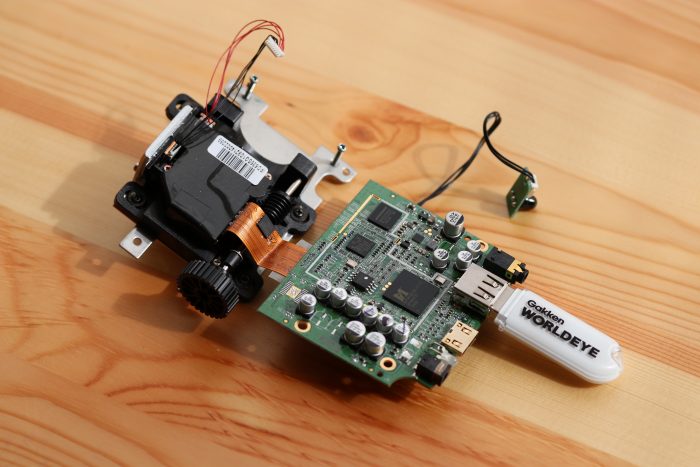
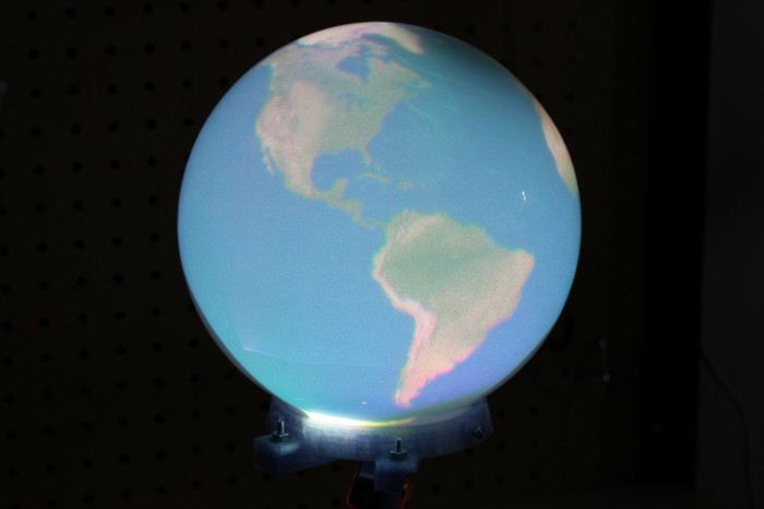
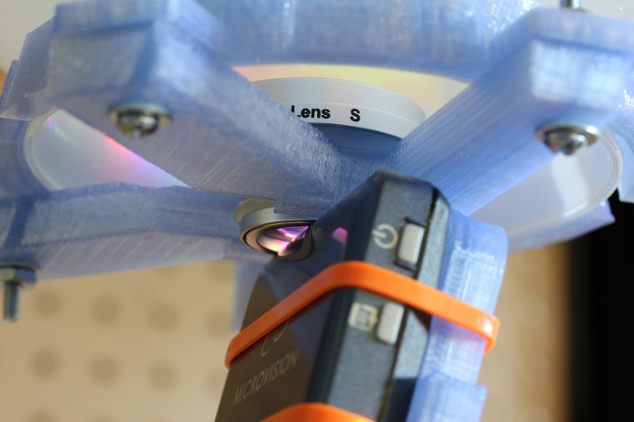
A few months ago Palmer Luckey gave me heads up that a company called Gakken in Japan had a consumer version of the idea and that like everything in the world, there were sellers on eBay and Amazon importing it into the US.  The Gakken Worldeye sounded like it could fulfill the dream of a desktop spherical display, so I bought one to use and another to tear down.  It ended up being a hemispherical display with a pretty decent projection surface but a terrible projector and even worse driving electronics.  The guts of the sphere are above.  There is a VGA resolution TI DLP that is cropped by the lens to a 480 pixel circle.  The Worldeye takes 720p input over HDMI, which is then downsampled and squashed horizontally to that circle by an MStar video bridge.  Between the poor projector resolution and the questionable resampling, the results look extremely blurry.

Sony spherical projector

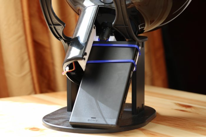
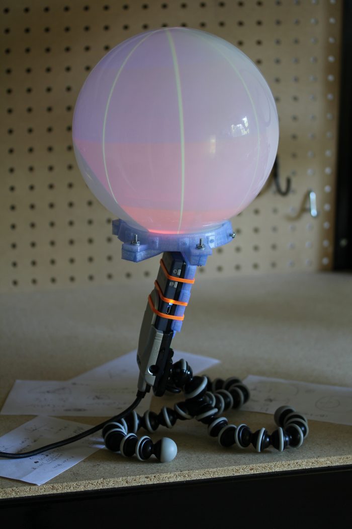
I figured it would be possible to improve on the sphere by taking advantage of the display surface and lens and swapping out the projector and electronics.  In the time since the ShowWX used in the Snow Globe was released, Microvision has developed higher resolution laser scanning projector modules in conjunction with Sony and others.  I picked up a Sony MP-CL1 with one of these modules, which is natively 1280×720.  This should have been a decent improvement over the 848×480 in the ShowWX.  I then CAD’d up and 3d printed a holder to mount it along with the original Worldeye lens into the globe.

Higher resolution Gakken Worldeye

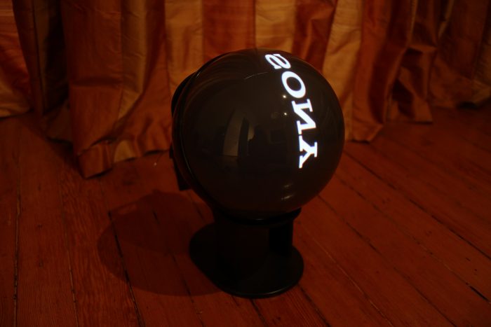
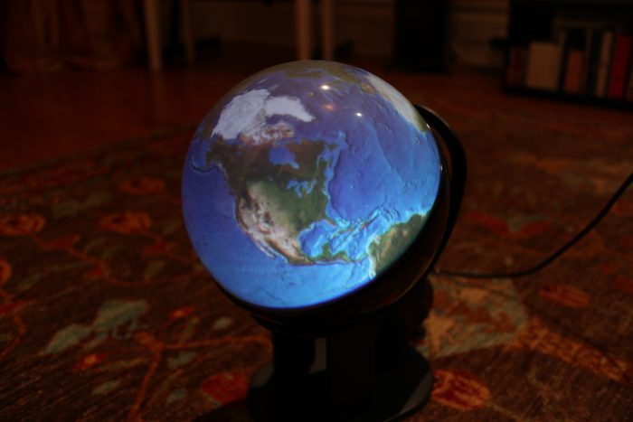
The results are a bit underwhelming.  The image looks better than the stock Worldeye, but still looks quite blurry.  I realized afterwards that the sphere diameter is too small to take advantage of the projector resolution.  At around a 5″ radius, the surface of the sphere is getting around 1.8 pixels per mm (assuming uniform distortion).  The laser beam coming out of the projector is well over 1 mm wide, and probably closer to 1.5mm.  This means that neighboring pixels are blending heavily into each other.  The lens MTF is probably also pretty poor, which doesn’t help the sharpness issue.  If you’re interested in trying this out anyway, the .scad and .stl files are up on Thingiverse and the code for the Science on a Snow Globe application to display equirectangular images and videos is on GitHub.  The conclusion to the opening prompt is that spherical displays are more accessible in 2018 than they were in 2011, but don’t seem to be any better quality.  Hopefully someone takes the initiative to solve this.

16 Comments on Snow Globe Redux: Gakken Worldeye Projector Upgrade

Satellites on a Snow Globe Spherical Display

Continuing on the theme of interesting things to do with an interactive globe, I added a live satellite tracking mode to sosg.  The program polls a local PREDICT server for location and visibility information about the satellites being tracked by it.  It draws the name of each satellite and the path it is following in red.  It also draws a little icon that turns green when the satellite is visible overhead. There is enough civilization in close proximity to my apartment that I can’t see actually see one pass by, but it is nice to know they are there above me.  As before, the ISC licensed code is available on github at git://github.com/nrpatel/SnowGlobe.git

9 Comments on Satellites on a Snow Globe Spherical Display

Science on a Snow Globe Spherical Display

Science On a Sphere is a NOAA project typically using four projectors to display planetary data on a six foot diameter sphere.  As a federal agency, NOAA publishes data that is not copyrightable.  These public domain datasets are pretty impressive, ranging from plate tectonics to solar storms.  They are also insanely high resolution, with mp4 videos and jpg images at 2048×1024 and 4096×2048.

To shrink this four projector, five computer, high resolution science center exhibit down to a picoprojector, old laptop, bathroom lighting fixture setup, I had to move beyond my unoptimized python scripts to SDL, OpenGL, libvlc, and GLSL.  I wrote a program called sosg, Science On a Snow Globe, which reads in images and videos and displays them in the correct format for Snow Globe.  Doing the equirectangular to fisheye transform in a fragment shader is extremely lightweight, even with GMA graphics.  Using libvlc makes video decoding quite performant as well, despite the resolution.

The program is the closest I’ve written to “shippable” in recent memory, but there are some rough spots.   I ran into a bottleneck trying to decode high resolution jpgs in real time, so currently sosg does not support the image slideshows that the full size SOS does.  It also doesn’t attempt to read in .sos playlist information.  Basically, it is not an SOS replacement, just a cheap and cheerful way to view planetary data on your desktop. Unlike the original, it is also available under a permissive license and can be cloned directly from git://github.com/nrpatel/SnowGlobe.git.

8 Comments on Science on a Snow Globe Spherical Display

Snow Globe: Part One, Cheap DIY Spherical Projection

Earth in Snow Globe

Since reading Snow Crash, I’ve been drawn to the idea of having my own personal Earth.  Because I’m stuck in reality and the virtual version of it is always 5 years away, I’m building a physical artifact that approximates the idea: an interactive spherical display.  This is of course something that exists and can likely be found at your local science center.  The ones they use are typically 30-100″ in diameter and cost enough that they don’t have prices publicly listed.  Snow Globe is my 8″ diameter version that costs around $200 to build if you didn’t buy a Microvision SHOWWX for $600 when they launched like I did.

Lens mount

The basic design here is to shoot a picoprojector through a 180° fisheye lens into a frosted glass globe.  The projector is a SHOWWX since I already have one, but it likely works better than any of the non-laser alternatives since you avoid having to deal with keeping the surface of the sphere focused.  Microvision also publishes some useful specs, and if you ask nicely, they’ll email you a .STL model of their projector.  The lens is an Opteka fisheye designed to be attached to handheld camcorders.  It is by far the cheapest 180° lens I could find with a large enough opening to project through.  The globe, as in my last dome based project is for use on lighting fixtures.  This time I bought one from the local hardware store for $6 instead of taking the one in my bathroom.

I’ve had a lot of fun recently copying keys and people, but my objective in building a 3D printer was to make it easier to do projects like this one.  Designing a model in OpenSCAD, printing it, tweaking it, and repeating as necessary is much simpler than any other fabrication technique I’m capable of.  In this case, I printed a mount that attaches the lens to the correct spot in front of the projector at a 12.15° angle to center the projected image.  I also printed brackets to attach the globe to the lens/projector mount.  The whole thing is sitting on a GorillaPod until I get around to building something more permanent.

Snow Globe

Actually calibrating a projector with slight pincushion through a $25 lens into a bathroom fixture attached together with some guesswork and a 3D printer is well beyond my linear algebra skill, so I simplified the calibration procedure down to four terms.  We need to find the radius in pixels of the circle being projected and the x and y position of the center of that circle for starters.  The more difficult part, which tested my extremely rusty memory of trigonometry is figuring out how to map the hemisphere coming out of the fisheye lens to the spherical display surface.  For that, we have a single number for the distance from the center of the sphere to the lens, in terms of a ratio of the projected radius.  The math is all available in the code, but the calibration script I wrote is pretty simple to use.  It uses pygame to project longitude lines and latitude color sections as in the image above.  You use the arrow keys to line up the longitude lines correctly to arrive at the x and y position, plus and minus keys to adjust the radius size until it fits the full visible area of the sphere, and 9 and 0 to adjust the lens offset until the latitudes look properly aligned.  What you end up with is close enough to correct to look good, though as you can see in the images, the projector doesn’t quite fit the lens or fill the sphere.  The script saves the calibration information in a pickle file for use elsewhere.

Projected sphere

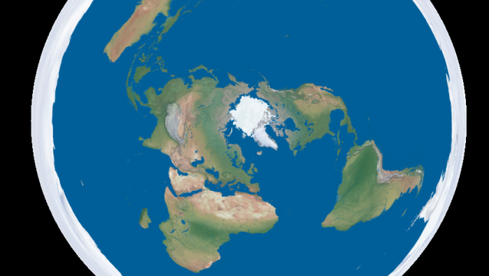
Going back to the initial goal, I wrote a script to turn equirectangular projected maps of the Earth into roughly azimuthal equidistant projected images calibrated for a Snow Globe like the one above.  There are plenty of maps of the former projection available freely, like Natural Earth and Blue Marble. Written in python, the script is quite slow, but it serves as a proof of concept.  The script, along with the calibration script and the models for the 3D printed mounts are all available on github.  I’ve finally fully accepted git and no longer see a point in attaching the files to these posts themselves.  I put a Part One in the title to warn you that this blog is going to be all Snow Globe all the time for the foreseeable future.  Up next is writing a faster interface to interactively display to it in real time, and if I think of a good way to do it, touch input is coming after that.

Download from github:
git://github.com/nrpatel/SnowGlobe.git

69 Comments on Snow Globe: Part One, Cheap DIY Spherical Projection

Easy Interactive Camera-Projector Homography in Python

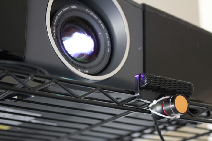
Camera and Projector

Math.  It turns out its not quite like riding a bike.  A year since college, and two since my last computer vision course, my knowledge of linear algebra is basically nil.  Several projects I’m stewing on are bottlenecked on this.  I decided to relearn some basics and create a tool I’ve wanted for a while, a method to quickly and easily calculate the homography between a camera and a projector.  That is, a transformation that allows you to map points from the camera plane to the display plane.  This opens up a world of possibilities, like virtual whiteboards and interactive displays.

I won’t go into detail about deriving the transformation matrix, as there is information elsewhere better than I could present.  The calculation requires four or more matching point pairs between the two planes.  Finding the points manually is a pain, so I wrote a script that uses Pygame and NumPy to do it interactively.  The script works as follows:

  1. Point an infrared camera at a projector screen, with both connected to the same computer.
  2. Run the script.
  3. Align an lit IR LED to the green X on the projector screen, and press any key.
  4. Repeat step 3 until you have four points (or more, depending on the script mode), at which point,
  5. The script will calculate the homography, print it out, and save it as a NumPy file.

The script in its current form uses any Pygame supported infrared camera.  This today is likely a modded PS3 Eye or other webcam, unless you’re lucky enough to have a Point Grey IR camera.  I do not, so I hot glued an IR filter from eBay to the front of my Eye, that I may have forgotten to return to CMU’s ECE Department when I graduated.  Floppy disk material and exposed film can also function as IR filters on the cheap,  just be sure to pop the visible light filter out of the camera first.

It would be overly optimistic of me to believe there are many people in the world with both the hardware and the desire to run this script.  Luckily, due to the magic of open source software and the modularity of Python, individual classes and methods from the file are potentially useful.  It should also relatively straightforward to modify to accept other types of input, like a regular webcam with color tracking or a Wii Remote.  I will add the latter myself if I can find a reasonable Python library to interface one with.

Once you have the transformation matrix, you can simply dot the matrix with the point from the camera to get the corresponding point on the projector.  The blackboard script, demonstrated by my roommate above and downloadable below shows a use case for this, a drawing app using an IR LED as a sort of spray can.  The meat of it, to convert a point from camera to projector coordinates, is basically:

# use homogeneous coordinates
p = numpy.array([point[0],point[1],1])
# convert the point from camera to display coordinates
p = numpy.dot(matrix,p)
# normalize it
point = (p[0]/p[2], p[1]/p[2])

The homography.py script takes the filename of the matrix file to output to as its only argument.  It also has an option, “-l”, that allows you to use four or more points randomly placed around the screen, rather than the four corner points.  This could come in handy if your camera doesn’t cover the entire field of view of the projector.  You can hit the right arrow key to skip points you can’t reach and escape to end and calculate.  The blackboard.py script takes the name of the file the homography script spits out as its only argument.  Both require Pygame 1.9 or newer, as it contains the camera module.  Both are also licensed for use under the ISC license, which is quite permissive.

nrp@Mediabox:~/Desktop$ python homography.py blah
First display point (0, 0)
Point from source (18, 143). Need more points? True
New display point (1920, 0)
Point from source (560, 137). Need more points? True
New display point (0, 1080)
Point from source (32, 446). Need more points? True
New display point (1920, 1080)
Point from source (559, 430). Need more points? False
Saving matrix to blah.npy
 array([[  3.37199729e+00,  -1.55801855e-01,  -3.84162860e+01],
       [  3.78207304e-02,   3.41647264e+00,  -4.89236361e+02],
       [ -6.36755677e-05,  -8.73581448e-05,   1.00000000e+00]])
nrp@Mediabox:~/Desktop$ python blackboard.py blah.npy

Download:
homography.py
blackboard.py

6 Comments on Easy Interactive Camera-Projector Homography in Python

Projecting Virtual Reality with a Microvision SHOWWX

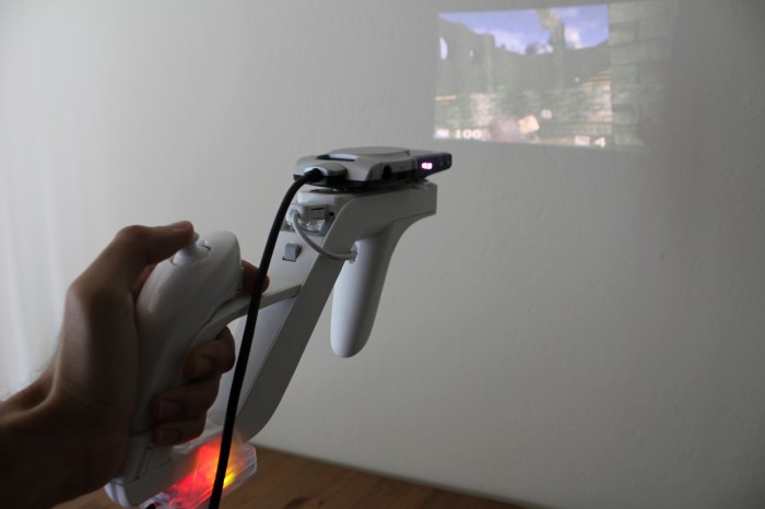
It’s bit of a stretch to call this Virtual Reality, in capitals no less, but I can’t think of another noun that fits it better.  This is the idea I have been hinting about, sprouted into a proof of concept.  By combining the stable positioning of the SpacePoint Fusion with the always in focus Microvision SHOWWX picoprojector, one can create a pretty convincing glasses-free virtual reality setup in any smallish dark room, like the bedroom in my Bay Area apartment.

Projecting Virtual Reality

This setup uses the SpacePoint to control the yaw, pitch, and roll of the camera, letting you look and aim around the virtual environment that is projected around you.  A Wii Remote and Nunchuk provide a joystick for movement and buttons for firing, jumping, and switching weapons.  All of the items are mounted to a Wii Zapper.  For now, it is annoyingly all wired to a laptop I carried around in a backpack.  Eventually, I’m planning on using a BeagleBoard and making the whole projector/computer/controller/gun setup self-contained.

The software is a hacked version of Cube, a lightweight open source first person shooter.  It’s no Crysis 2, but it runs well on Mesa on integrated graphics, and it’s a lot easier to modify for this purpose than Quake 3.  Input is via libhid for the SpacePoint and CWiid for the Wiimote.  All in all, it actually works pretty well.  The narrow field of view and immersiveness (a word, despite what my dictionary claims) makes playing an FPS quite a bit scarier for those who are easily spooked, like yours truly.  There is some serious potential in the horror/zombie/velociraptor genres for a device like this, if anyone is interested in designing a game.

This is just the start, of course.  I know I say that a lot, and there are about a dozen projects on this blog I’ve abandoned, but I think this one will hold my attention for a while.  I hate showing off anything without source code, so even though it will likely not be useful to anyone, I’ve attached the patch against the final release of Cube.

Download:
projecting.diff

28 Comments on Projecting Virtual Reality with a Microvision SHOWWX

Evil Eye: Microvision SHOWWX as a Face Tracking Eyeball

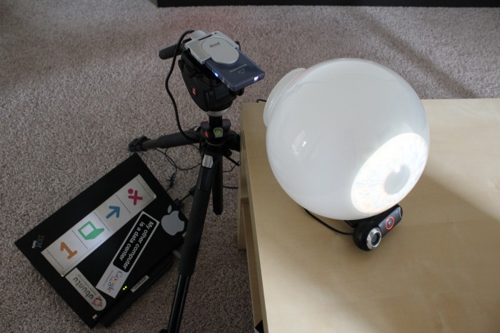
This idea, like most good ones, came to me while I was in my bathroom.  I recently took delivery of a Microvision SHOWWX laser pico projector, and I was trying to come up with a quick project to show the cool stuff it could do.  I noticed that the light above my mirror was diffused by a large frosted glass dome, which led to this strange project.  It’ll probably make more sense around Halloween.

Microvision SHOWWX Setup

The software is pretty similar to what I wrote the last time I did face tracking:  OpenCV’s very convenient Haar feature detection along with Pygame to do the image display.  I tried taking a picture of my own eye, but Flickr user Sarah Cartwright’s is much more photogenic and available under Creative Commons Attribution-Share Alike.

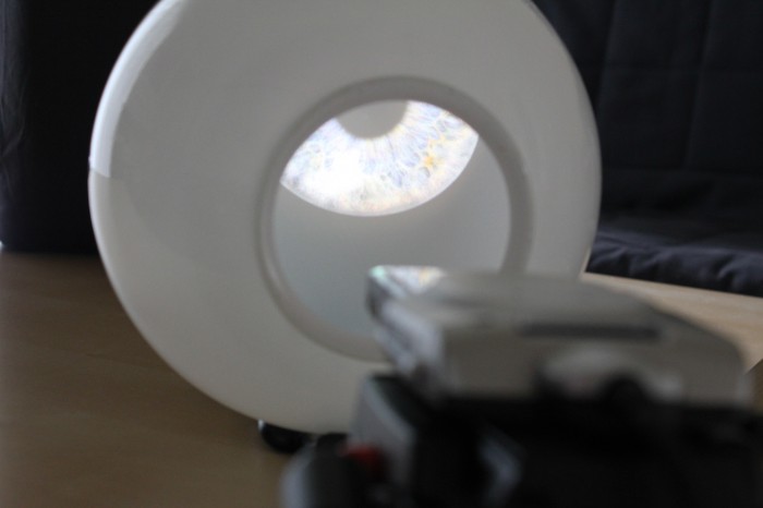
Inside the Eye

A regular pico projector would probably work as well, but the contrast ratio on this thing means it looks like the iris is being projected by itself.  I have some much cooler projects planned that will really take advantage of the focus free nature of the laser projector.  In the mean time, the code for this project is available below.  The image is CC A-SA, the code is public domain, and the Haar file is Intel License Agreement like the rest of OpenCV.  I also attached the Python script itself for perusal by search engines or folks who just want to see the code.

Download:
EvilEye.zip
EvilEye.py

5 Comments on Evil Eye: Microvision SHOWWX as a Face Tracking Eyeball